3
DIP Switches
Use the DIP switches to configure logic settings and mute button behavior.
The DIP switches are covered with a piece of clear tape at the factory.
Remove tape to modify the switch settings.
Note: Bottom cover must be closed for microphone to function.
OFF (factory default) ON
1 Momentary Toggle
2 Push-to-mute Push-to-talk
3 Mute button enabled, LED illu-
minates when mic is active
Disable mute button (micro-
phone always on), logic controls
LED
4 -- --
Wiring Diagram
NOTE: Audio and logic ground are connected at microphone base.
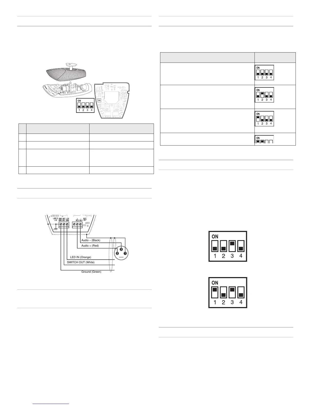
Mute Button Configuration
Use DIP switches 1 and 2 to configure the mute button, as follows.
Be sure to set DIP switch 3 off (factory default) so that the mute button
controls audio from the microphone.
Switch Function DIP Switch Setting
Momentary: push-to-mute (as shipped).
Momentary: push-to-talk
Toggle: (Push On/Push Off): Mic is active when
powered on
Toggle: (Push On/Push Off): Mic is mute when
powered on
Connecting to an Automatic Mixer
Use these settings if connecting the microphone to an automatic mixer or
other device that mutes audio and controls the LED.
1. Connect logic leads to the automatic mixer. Connect the LED IN to
the gate output to illuminate the LED when that channel is gated on.
2. Set DIP switch 3 on. This disbles the mute button (the microphone
passes audio regardless of whether the button is pressed or not).
3. Set DIP switch 1 to configure how the mute but-
ton sends SWITCH OUT logic:
Momentary: push = 0 Vdc, release = 5 Vdc
Toggle: initial = 5 Vdc, push = 0 Vdc
Logic Wiring
Green (LOGIC GROUND): Connects to the logic ground of an automatic
mixer, switcher, or other equipment.
Orange (LED IN): Set DIP switch 3 on to use LED IN. When shorted to
LOGIC GROUND, the LED turns on.
White (SWITCH OUT): Provides TTL logic (0 Vdc or 5 Vdc) in response
to the mute button. Set DIP switch 1 for momentary or toggle. When phan-
tom power is applied, logic initializes high (5 Vdc). DIP switch 2 has no
effect on SWITCH OUT.
Changing SWITCH OUT to Always
Momentary
Use the following modification in situations where your logic interface
requires momentary closure of the SWITCH OUT, but you want the mute
button to toggle the microphone (DIP switch 1 ON, 3 OFF):
1. Access the circuit board inside the microphone base.
2. Remove the resistor at R45 and reinstall it at location R46.