19
Hardware Interface Description
MXWANI8
Input: 100-240V ~ TBD A max. 50/60 Hz
Class 0 PoEuplink
1234
MXWANI8
Input: 100-240V ~ TBD A max. 50/60 Hz
Class 0 PoEuplink
1234
①
②
③
④
⑤ ⑥
⑦⑧
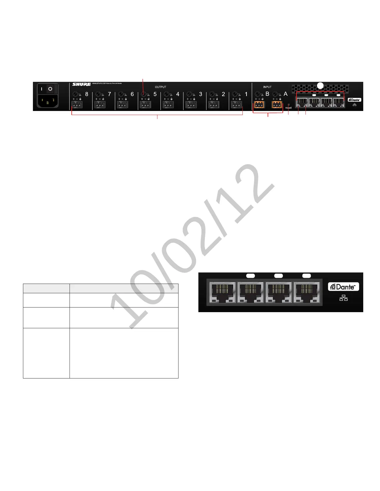
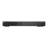
① AC Power
IEC connector 100 - 240 V AC.
② Power Switch
Powers the unit on or off.
③ Output Block Connectors (1-8)
Three-pin, low-voltage connector provides a direct output for each
channel.
④ Chassis Ground
Use to directly ground the cable shield to the chassis.
⑤ Input Block Connectors (A,B)
Three-pin, low-voltage connector adds line- or aux-level analog signals
to the digital network.
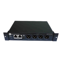
Back Panel
⑥ Reset Button
Press and hold the button for five seconds to reboot the device with
factory default settings.
⑦ Network Status LED (Green)
Off = no network link
On = network link established
Flashing = network link active
⑧ Network Speed LED (Amber)
Off = 10/100 Mbps
On = 1 Gbps
⑨ Network Interface
Digital Audio connection and networking capabilities with shielded Cat-
5e (or higher) cable.
⑨
4-Port Network Interface
Port Description
Port 1 (PoE)
Provides Power over Ethernet (PoE) for the
Shure MXWAPT Access Point.
Ports 2 and 3
Connects to an additional ANI for clock syn-
chronization, to an MXW charger, or to a con-
trol system.
Port 4 (Uplink)
By default, this port functions the same as
ports 2 and 3. However, it can be configured to
provide password protected uplink to corporate
LAN without network audio traffic. When Port 4
Uplink is enabled from the GUI, it only provides
access to the GUI, blocking data to the Shure
Discovery Application, Dante Controller and
Dante Virtual Soundcard.