2
Custo
m S
witch Modifications
S4
i
s a
vailabl
e f
or
c
usto
m l
ogi
c m
odifications
. W
he
n S
4 i
s i
n
the
O
N p
osition
, p
a
d W
4 i
s c
onnecte
d to p
a
d W
5.
NOTE:
For technical data by Fax, phone 1-800-488-3297 and
follow
the recorded
instructions. For additional technical assis
-
tance, phone Shure at (847) 866-2200. In Europe, phone
49-7131-72140.
REPLACEMENT PARTS AND ACCESSORIES
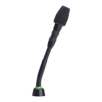
Snap–Fit Foam Windscreen (4 per pkg.) RK412WS.
. . . . .
Foam Ball Windscreen (4 per pkg.) A99WS.
. . . . . . . . . . . . .
Locking Metal Windscreen A412MWS.
. . . . . . . . . . . . . . . . . .
Replacement 3 m (10 ft) XLR Cable C120.
. . . . . . . . . . . . . .
Custom Logic Cable (specify length) 15A523/1.
. . . . . . . . . .
Omnidirectional Cartridge R183B.
. . . . . . . . . . . . . . . . . . . . .
Supercardioid Cartridge R184B.
. . . . . . . . . . . . . . . . . . . . . .
Cardioid Cartridge R185B.
. . . . . . . . . . . . . . . . . . . . . . . . . . . .
Base Plate Bumpers 80A8053A.
. . . . . . . . . . . . . . . . . . . . . . .
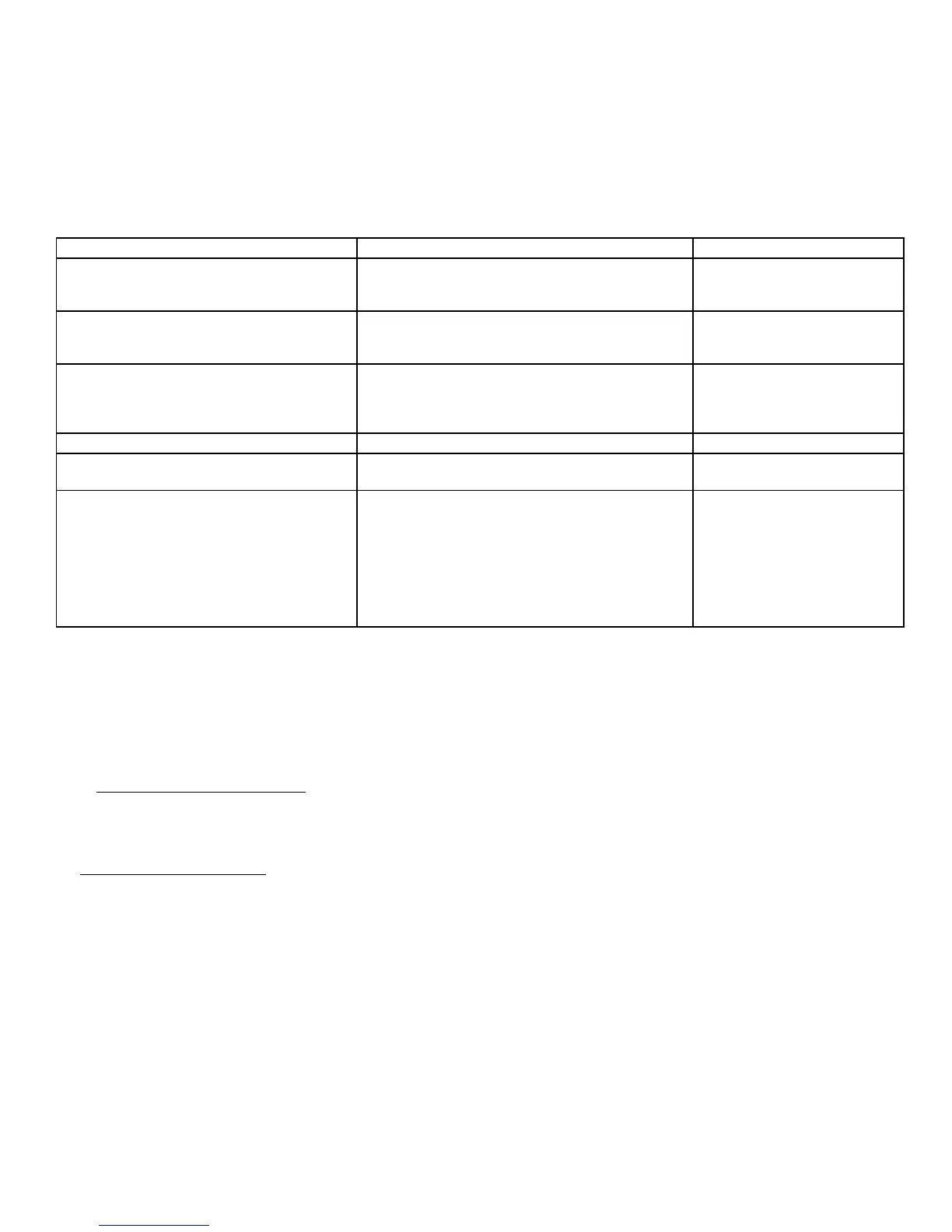
DESIRED MICROPHONE FUNCTION USER ACTION/LED DISPLAY DIP SWITCH SETTINGS
Push to Mute (As Shipped)
Press and hold switch to temporarily mute micro
-
phone; release switch to unmute
LED turns on when microphone is active
S1 = OFF
S2 = OFF
S3 = OFF
Push to T
alk
Press and hold switch to activate microphone; re
-
lease switch to mute
LED turns on when microphone is active
S1 = OFF
S2 = ON
S3 = OFF
Push On/Push Off
Press switch to toggle microphone on or of
f
LED turns on when microphone is active
S1 = ON,
S2 = ON for muted initial state
S2 = OFF for active initial state
S3 = OFF
Switch Deactivated, Mic Always Active
No action, LED Always OFF S3 = ON
Switch Deactivated, Mic Always Active
Short LED IN terminal to LOGIC GROUND terminal
LED Always ON
S3 = ON
Automatic Mixer Mode
If S1=OFF
, SWITCH OUT signal will be momentarily
logic low when switch is pressed
If S1=ON, SWITCH OUT signal will be latching logic
low when switch is pressed
Connec
t S
WITCH OUT signa
l t
o various logic inputs
o
f a
utomatic mixe
r f
or custo
m f
unctions
Connect mixer channel GA
TE OUT to microphone
LED IN. LED on microphone turns on when its
channel is gated on
S1 = ON or OFF
S3 = ON
SPECIFICATIONS
Frequency Response (Figure 3)
50 to 17,000 Hz
Polar Pattern (Figure 4)
Output Impedance
EIA Rated at 150 Ω (180 Ω actual)
Open Circuit Sensitivity
At 1 kHz, ref. 1 V per microbar*
Cardioid: –53.5 dBV (2.11 mV)
Supercardioid: –52.5 dBV (2.37 mV)
Omnidirectional: –48.0 dBV (3.98 mV)
*1 microbar = 74 dB SPL
At 1 kHz, ref. 1 V per Pascal
Cardioid: –33.5 dBV (21.1 mV)
Supercardioid: –32.5 dBV (23.7 mV)
Omnidirectional: –28.0 dBV (39.8 mV)
*1 Pascal = 94 dB SPL
Maximum SPL (1 kHz at 1% THD, 1 kΩ load)
Cardioid: 123.0 dB
Supercardioid: 122.0 dB
Omnidirectional:
117.5 dB
Equivalent Output Noise (A-weighted)
Cardioid: 29.0 dB SPL
Supercardioid: 28.0 dB SPL
Omnidirectional:
23.6 dB SPL
Signal to Noise Ratio (referenced at 94 dB SPL)
Cardioid: 65.0 dB
Supercardioid: 66.0 dB
Omnidirectional:
70.5 dB
Dynamic Range with 1 kΩ Load
94.0 dB
Common Mode Rejection
45.0 dB minimum
Mute Switch Attenuation
50.0 dB minimum
Preamplifier Output Clipping Level (1% THD)
–6.0 dBV (0.5 V)
Polarity
Positive sound pressure on diaphragm produces
positive voltage on pin 2 relative to pin 3 of XLR
output connector.
Power Requirements
11 to 52 Vdc phantom, 2.0 mA
Environmental Requirements
Operating
T
emperature Range: –18
° to
57
°
C (0
°
to
135
° F)
Relative Humidity: 0 to 95%
Dimensions (Figure 5)
Weight
0.81 kg (1.80 lbs) net
1.25 kg (2.77 lbs) packaged
Cable Type
The
a
ttache
d c
usto
m c
abl
e c
ontains
a s
hielde
d a
udio
pair
a
n
d t
hre
e u
nshielde
d c
onductor
s f
o
r l
ogic
c
ontrol.
Overall diameter = 0.6 mm (0.165 in.)
Certification
Conforms
to European Union directives, eligible to
bear CE marking; meets European Union EMC
Immunity
Requirements (EN 50 082–1, 1992); RF
radiated
(IEC 801–3); ESD (IEC 801–2); EFT
(IEC
801–4).