4
CIRCUIT DESCRIPTION
A block diagram of the SM81 is shown in Figure 6. The ca-
pacitor cartridge is followed by a switch-controlled capacitive
attenuator stage which provides for 10 dB attenuation at the
cartridge output. The signal is fed to a field-effect transistor
(FET) impedance conversion stage. The FET output drives an
active low-frequency response (high-pass) filter controlled by
a three-position switch. The filter output from a compound tran-
sistor, Class A, emitter-follower amplifier is transformer-
coupled, providing a balanced output to the RFI protection filter
at the microphone connector. An active, constant-current
power supply circuit regulates the phantom voltage, allowing
the SM81 to operate over a very wide range of voltages. A re-
verse voltage protection diode guards against miswired cables
and equipment.
TROUBLESHOOTING
If the SM81 fails to operate properly, verify that the micro-
phone is powered properly.
1. Check the power supply output voltage to the microphone.
For the Shure PS1A, this should be 21.5 ± 1.5 Vdc open
circuit.
2. Check the voltage on microphone connector pins 2 and 3
(at back of connector; cable connector disassembled from
shell but connected to microphone). The voltage at pins 2
and 3 with reference to pin 1 should be between 11 and 52
Vdc.
Due to its high packing density and circuit complexity, dis-
assembly of the SM81 is not recommended. Contact Shure’s
Service Department if problems persist.
ARCHITECTS’ SPECIFICATION
The microphone shall be a condenser microphone with a
frequency response of 20 to 20,000 Hz. It shall have a unidirec-
tional pickup characteristic, with cancellation at the sides of 6
dB and a minimum cancellation at the rear of 15 dB at 1 kHz.
The microphone shall have a rated output impedance of 150 Ω
for connection to microphone inputs of 150 ohms or higher. The
open circuit voltage shall be –65 dB (0.56 mV) (0 dB equals 1
volt per microbar).
The microphone shall contain a three-position low-freq-
uency response switch and a lockable 10 dB attenuator pad.
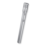
The overall dimensions shall be 212 mm (8-11/32 in.) in
length by 23.5 mm (15/16 in.) in diameter. The handle diameter
shall be 20.1 mm (25/32 in.). The weight shall be 230 grams
(8 oz).
The microphone shall be capable of being powered by a
phantom power supply with an output of 11 to 52 Vdc, or by a
mixer, audio console or tape recorder capable of supplying 11
to 52 Vdc.
The microphone shall be a Shure Model SM81.
FURNISHED ACCESSORIES
Swivel Adapter A57F. . . . . . . . . . . . . . . . . . . . . . . . . . . . . . . .
10 dB Attenuator Lock 34A830. . . . . . . . . . . . . . . . . . . . . . . . .
Carrying/Storage Case 65A1797. . . . . . . . . . . . . . . . . . . . . . .
Windscreen 49A111. . . . . . . . . . . . . . . . . . . . . . . . . . . . . . . . . .
OPTIONAL ACCESSORIES
Pop-Filter Grille A81G. . . . . . . . . . . . . . . . . . . . . . . . . . . . . . . .
Heavy-Duty Windscreen A81WS. . . . . . . . . . . . . . . . . . . . . . .
Tripod Microphone Stand (4.3 m [14 ft]) S15A. . . . . . . . . . . .
Stereo Microphone Adapter A27M. . . . . . . . . . . . . . . . . . . . . .
Cable (7.6m [25ft]) C25F. . . . . . . . . . . . . . . . . . . . . . . . . . . . . .
Phantom Power Supply PS1A. . . . . . . . . . . . . . . . . . . . . . . . .
REPLACEMENT PARTS
Cartridge and Grille Assembly R104. . . . . . . . . . . . . . . . . . .

 Loading...