T
Tyler MillerJul 30, 2025
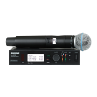
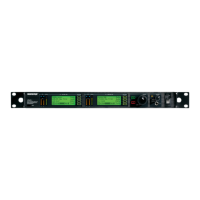
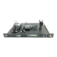
Why is my Shure UC Microphone system signal noisy?
- KKathleen ChanJul 30, 2025
If your Shure Microphone system receiver's signal is noisy or contains extraneous sounds while the transmitter is on, first check the transmitter's power/battery fuel gauge and replace the battery if the power is low. Then, try removing any local sources of RF interference, such as lighting equipment. If you're using a guitar or another instrument, ensure it's connected to the UC1 with a Shure WA302 adapter cable. It's also possible that two transmitters are operating on the same frequency, so locate and turn one off or change its frequency. Finally, the signal may be too weak, so reposition the antennas closer to the transmitter and adjust the receiver's squelch control.