6 – INSTRUCTIONS FOR USE
6.1 – Turning on
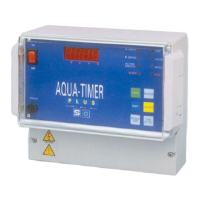
The controller is turned on via the main switch ON (I) - OFF (0) situated on the front panel. This switch acts on both
supply conductors.
The supply voltage must be 230 Vac - 50 Hz. (on demand 24 Vac – 50 Hz. )
Check the supply voltage using the adhesive labels situated on the cover of the connections.
6.2 – Programming of the operative modalities
Before proceeding to the programming of Aqua Timer Plus, it must be checked that the distributor cams are positioned
at the limit cycle position. If operations are to be carried out on the controller before its installation, that is without the
distributor connected, the limit switch entry must be closed with a connection bridge. If this simple rule is not
respected, Aqua Timer Plus will accept all the new programming, but will not be able to carry out the normal
operations needed during the service.
The programming will be carried out via the keypad on the front of the controller.
Aqua Timer Plus has the following operative modalities:
Tab. 4 – Table of the operative modalities
The selection takes place according to the sequence shown below:
Tab. 5 – Selection of the operative modalities
If the protection code has been programmed through the programming function SC07 (see par. 6.3), the procedure
described in tab. 5 varies as follows: