I 21
9 ELECTRICAL CONNECTION (Only for the PREMIUM rangeof Siber DF EVO )
9.1 MAINS CONNECTION
The electrical installation must correctly comply with the relevant standards.
Warning! The fans and the control circuit shall operate at 230 V. If handling or maintenance work is carried out, the unit must
be disconnected from the mains.
HOSE IDENTIFICATION COLOURS
BROWN Line
BLUE Neutral
GREEN / YELLOW Earth
CONNECTOR DESCRIPTION PLATE
PIN 11 Not used
PIN 12 Common selector 3V V1 230V X-9
PIN 13 Selector 3V V2 X-9
PIN 14 Selector 3V V3 X-9
PIN 15 Preheating output 230 V X-17
PIN 16 Preheating output Ground X-17
PIN 17 Preheating output Neutral X-17
PIN 18 Output 230 V Close Canadian Well Actuator X-28
PIN 19 Output 230 V Open Canadian Well Actuator X-28
PIN 20 Neutral Output Canadian Well Actuator X-28
CONNECTOR DESCRIPTION PLATE
PIN 1 Home automation input 10 v X-26
PIN 2 Home automation input 0V X-26
PIN 3 Home automation dry contact input X-25
PIN 4 Home automation dry contact input X-25
PIN 5 Forecast probe external Canadian well Forecast
PIN 6 Forecast probe external Canadian well Forecast
PIN 7 Post-heating signal output 10V X-16
PIN 8 Post-heating signal output 0V X-16
PIN 9 Mirror mode NO/NC X-32
PIN 10 Mirror mode NO/NC X-32
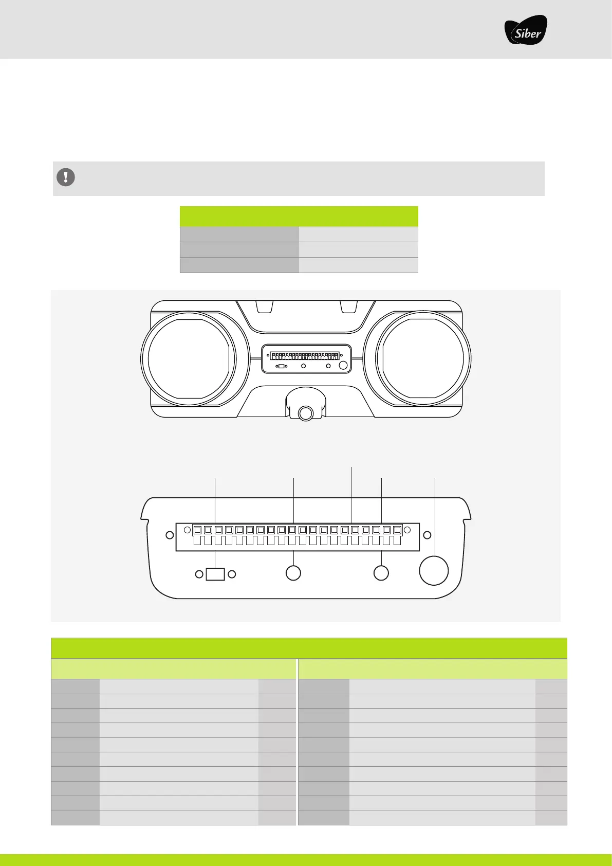
NUMBERING AND DESCRIPTION OF PIN CONNECTORS
Feed hosepassage
Antenna
20-pin connector
Multitiled green
running red failure
USB Type B connector PC
communication
1 2 3 4 5 6 7 8 9 10 11 12 13 14 15 16 17 18 19 20
1 2 3 4 5 6 7 8 9 10 11 12 13 14 15 16 17 18 19 20
Integrated smart control card.