28 ATS115-ATS115Plus User’s Manual
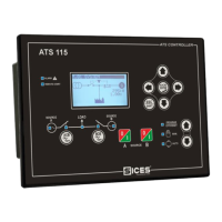
In order to activate the mode, press the ACK/ENTER button. A menu will help to select the
function required.
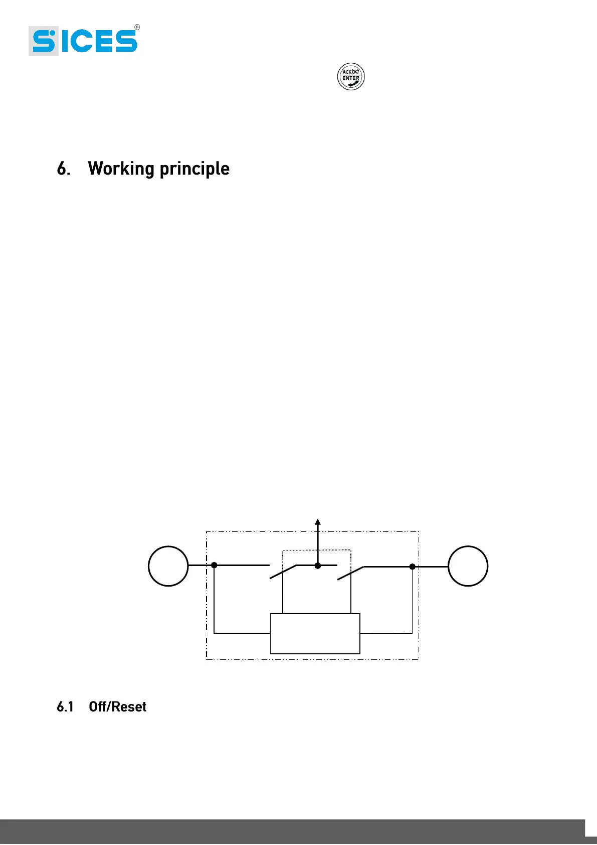
Below you can find the components of a standard switch system composed by a “Load” line (the load
that you want to supply) and two other “Source” lines A and B that can be both “Mains” and “Genset”
(with alternator and drive oil mechanic engine) and a control panel that includes: an ACB contactor for
the Source A management, a BCB contactor for the Source B management, an ATS115-ATS115
Plus
controller for the control of the electric grids and a series of components for the management of the
auxiliary parts (relay, fuses, terminals, etc…).
The two source lines can be configured (by means of the operating panel) to be used whether as mains
or as genset. Therefore, it is possible to manage three different types of systems:
System with one mains and one genset.
System with two gensets.
System with two mains.
The changeover, which is the switch of the load from Source A and Source B and/or vice versa, is
carried out by mechanically and electrically interlocked contactors, supplied by the same line but
managed by the device for what concerns the closing and/or the opening.
The controller does not manage the start/stop sequences, but makes available an output that demands
the start (activated output) or stop (deactivated output) each source. The external control unit will have
to manage the engine sequence when receiving this input command.
In this mode, the Load is usually supplied by the source set as Mains and with the related ACB or
BCB contactor closed. The Load supply is guaranteed until the contactor remains closed and supplied
by the Mains, with the exception of the system with two Gensets, where both contactors are opened
and the Load remains disconnected. If there is a Blackout on the Mains, the Load will stay
disconnected and the possible Genset stopped.
ATS115-
ATS115
Plus