56 GC315xx and GC400xx Technical Manual
The device is provided with three inputs designed for the connection to the resistive-type
sensors JM-2, JM-3, JM-4 and one JL-4, powered (as an alternative to using it a +D signal).
You can also use an optional DIVIT external expansion module and two DIGRIN or DITHERM
expansion modules connected by CAN-BUS to acquire 4 more voltage or current signals and
up to 6 temperatures. As GC315 does not have CANBUS, it can use the expansion modules
DIVIT, DIGRIN and DITHERM.
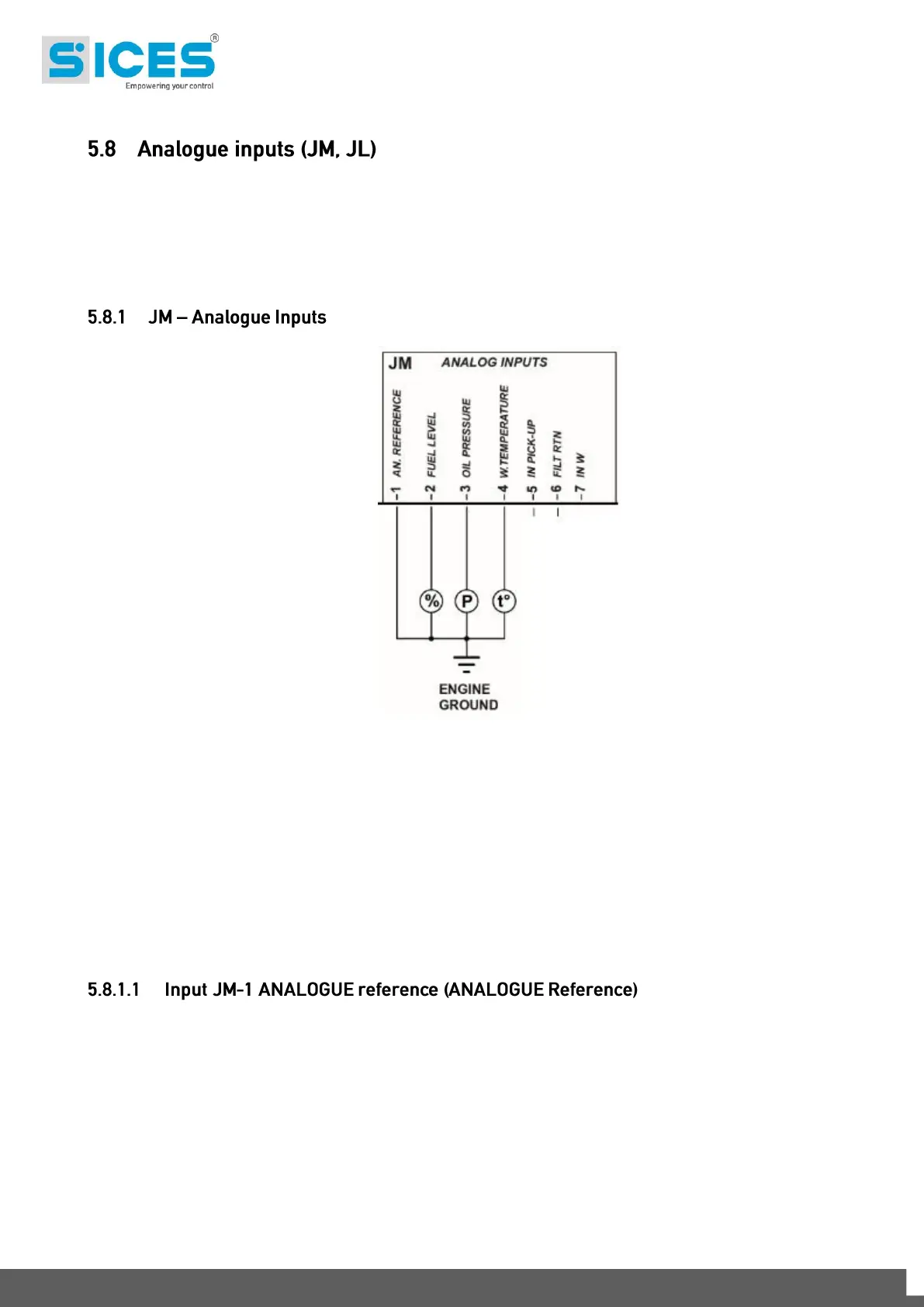
The device is equipped with three inputs designed for the connection to resistive-type sensors
JM-2, JM-3, JM-4. There is also an input for the measurement of their common ground
potential JM-1.
The four values of the voltage measured on terminals, and their related value of sensors
resistance, are displayed on page S.15.
It’s possible also to configure the three inputs JM-2, JM-3 and JM-4 singularly as additional
digital inputs. In order to activate the input, you need to connect it to the ground, and let it
floating to deactivate it. They will appear in the configuration menu of the digital inputs and
they will be managed exactly as the other inputs; see par. 5.5.3. If one or more inputs are
configured as digital inputs, their statuses is displayed on page S.11 (0=input not active,
1=input active). The inputs that are not configured as digital will be displayed with a hyphen.
It is not a real measure input: it is used together with the three inputs for resistive sensors and
has not effect on JL-4. Its purpose is to compensate for the lack of equipotentiality between
electric earthing of the device (GND terminal) and of the electric panel and electric earthing of
the genset, usually generated by the voltage drop on the connection cables; particularly, this
happens when the connections between electric panel and engine are long and when there is
a power flow in the battery minus and earthing connections, for example due to the presence
of the battery recharge device inside the electric panel.
The system is able to efficiently compensate for both positive and negative potentials, ranging
between -2.7VDC and +4VDC, with sensors resistance values of 100 ohm. The range of
compensation increases for lower resistance values and decreases for higher values of
 Loading...