Home
Sices
Controller
GC315
Sices GC315 User Manual
5
of 1
of 1 rating
213 pages
Give review
Manual
Specs
To Next Page
To Next Page
To Previous Page
To Previous Page
Loading...
90
GC315xx and GC400xx Technical Manual
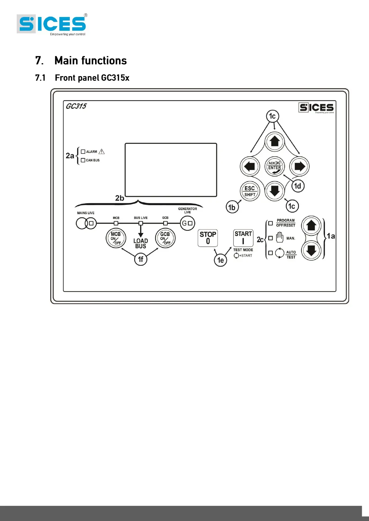
Fig. 1
–
Front Panel GC31
5x
KEY
1
- Pushbutt
ons
2
- Indicators
The controls consist of
12 buttons (
1a, 1b, 1c, 1d, 1
e, 1f
).
The front panel also has s
om
e luminous indicators (
2a, 2b, 2c
).
89
91
Table of Contents
Summary
3
Index
9
Nomenclature
16
Information on Safety
17
Introduction and Prerequisites
17
Switch SW1
18
Notes on the Configuration of the Device Parameters
18
Definitions
18
Conventions
19
Software Revisions
19
Views of the Device
20
Technical Features
24
Measurement Resolution
27
Additional Characteristics
27
Installation
28
Mounting
28
Wiring
28
Connections and In/Out Configuration
29
Basic Diagrams
30
Functional Earth (JC)
31
Device (JD) Supply
31
Digital Inputs (JN, JM)
32
JN - Digital Inputs
32
Virtual Digital Inputs
33
Configuration of the Digital Inputs
34
Digital Inputs (JL, JI, JE)
40
Engine Commands (JL)
40
JL-2 Common Plus Common Positive
40
Basic Diagram for Switching off When De-Energizing
40
JL-1 Start Command for the Engine Starter Motor
41
JL-3 Fuel Solenoid Command
41
JL-4 +D Energizing and Checking the Operation of Recharge Alternator
42
Outputs for JI Loads Change-Over Command
43
Auxiliary Outputs (JE)
44
Digital Outputs Configuration
45
Generator Faults Table
48
Engine Faults Table
49
Speed Controller Faults
49
And/Or Logics
50
Fuel Faults
50
Breakers Faults
50
List of the Internal States Available for the AND/OR Logics
52
Engine Rotational Speed Measurement (Pick-Up or W) JM-5, JM-6, JM-7
54
Magnetic Pick-Up
54
W Signal
55
Revolutions Measurement from Frequency
55
Analogue Inputs (JM, JL)
56
JM - Analogue Inputs
56
Input JM-1 Analogue Reference
56
Input JM-2 (FL, Fuel Level)
57
JM-3 (OP Oil Pressure)
57
Input JM-4 (CT Coolant Temperature)
57
JL-4 Analogue Input
57
Configuration of Analogue Inputs
58
List of Functions that Can be Associated to the Gc315X ANALOGUE Inputs
60
List of Functions that Can be Associated to the Gc400X ANALOGUE Inputs
60
Virtual Analogue Inputs
61
Conversion Curves
63
Analogue Inputs (JQ, JR)
65
Analogue Outputs on the Controller
65
Configuration of the Analogue Outputs
65
Optional Additional Modules
66
Connection to the Public Electric Mains/Parallel Bars (JH)
67
Measurement of the Mains Neutral
68
Connection to the Genset (JG)
68
Measurement of the Generator Neutral
69
Current Transformer Connection (JF)
70
Auxiliary Current
71
Difference Current
71
Communication
72
Serial Port 1 RS232 (JA)
72
Serial Port 2 RS485 (JO)
73
Usb (Jb)
74
Ethernet (JS)
75
CAN-BUS (JO) Connection
77
CAN-BUS (JP) Connection
78
Link Controllers
79
HW Configuration
80
SIM Insertion
81
GSM E GPS Antenna
82
Warning LED
82
Internal Battery as Option
83
Connection/Disconnection and Recharge of the Internal Battery
84
Parameters Configuration
85
GPRS/GSM Modem and SMS Messages
85
GPRS Configuration
86
GPS Receiver
86
“Si.mo.ne” System
87
Energy Saving Mode
88
Main Functions
90
Front Panel Diagrams
90
Selector
93
Indicators
96
Multifunctional Display
98
LCD Lighting
98
Contrast Adjustment
98
Mode Navigation
98
Display Area Layout
99
Top Status Bar
100
Display Mode
101
Programming (P.XX)
101
Organization
101
Protection Password
102
Operating Procedure
104
Access to Programming
105
Menu Selection
105
Parameters Selection
105
Modify a Parameter
106
Set up Limits
107
Exit from Programming
107
Loading Default Values
107
Status Information (S.XX)
108
S.01 Status
108
S.02 Anomalies
108
S.03 Serial Communication
109
S.04 Serial Communication (Gc400X)
109
S.04/S.05 Network
110
S.05/S.07 Can-Bus
110
S.06/S.03 Board
111
S.07-08-09/S.08-09-10 General Status
111
S.10 Fuel Pump
111
E.11 Fuel Pump
111
S.11 Digital Inputs
112
S.12 Digital Inputs
112
S.13 Digital Inputs
112
S.14 Digital Outputs
113
S.15 Analogue Inputs
113
S.16 Analogue Inputs 2 / S.17 Analogue Inputs 3
113
S.18 Analogue Outputs
113
S.18/S.19 Analogue Outputs
114
S.20 Mains Protection
114
S.20/S.20 Si.mo.ne
114
Electrical Measurements (M.XX)/M.01 System
114
M.02 Mains/Bars
115
M.03 Mains/Bars
115
M.04/M.05 Generator
115
M.06 Currents
116
M.07 Powers 1
116
M.08 Powers 2
116
M.09 Energy
116
M.10 Power 2
117
M.11 Aux Measure
117
M.12 Regolations
117
Engine Measurements
118
M.13 Synchronization
118
M.13 Parallel
118
E.01 Engine 1
118
E.02 Engine 2
119
E.03 Counters
119
E.04 Geraflex
119
E.04 Can-Bus/E.05 Can-Bus 1
119
E.05/E.06 Can-Bus 2
120
E.06/E.07 Can-Bus 3
120
E.07/E.08 Can-Bus 4
120
E.08/E.09 Can-Bus 5
121
E.09/E.10 Can-Bus 6
121
Measures from CAN-BUS PMCB
122
E.10-11-12/E.12-13-14 External Measures
122
E.13 Maintenance
122
B.01 Mc100/Btb100
122
B.06 Load Management
123
B.07 Load Management
123
History Logs (H.XX)
124
Log Selection
125
Events Pages
125
Pages for Analogues
128
Fast Analogue Logs
129
Slow Analogue Logs
129
Locked Recordings
129
Pages for Peaks
129
Engine Diagnostics Pages (DTC)
130
Exit from Archives Visualization
131
Reset Archives to Zero
131
Selection of the Language
132
Working Sequence
133
Operating Modes
133
Mains
136
Internal Sensor
137
Frequency Check
138
Voltages Check
139
Asymmetry Check
140
Rotation Direction Check
140
Internal Sensor Status
140
External Sensor
141
Mains Global Status
141
Communication and Events
141
Generator
142
Frequency
142
Voltages
143
Automatic Intervention of the Generator Inhibited
145
Overview
145
Differences between Mains Simulation and Inhibition
146
Inhibition from Contact
146
Inhibition from Clock
146
Engine Running/Stopped Status Acknowledgement
147
Engine Commands
148
Manual Control Sequence
149
Start-Up
149
Stop
152
Use of Two Fleets of Batteries
152
Standard Procedure
153
Communication and Events Record
154
Emergency Procedure
154
Breakers Management
156
Digital Outputs
156
Digital Inputs
157
Acquiring Breakers Status
157
Temporary Override of Breakers Commands
157
Manual Commands for Breakers
157
Synchronisation Request
158
Off/Reset Management Logic
158
MAN Management Logic
158
Switching Logic in Auto Mode
159
Switch
159
Switch Management
159
Automatic Power Delivery of the Generator Inhibited
159
Anomalies
162
Silencing the Horn
163
Acknowledging Anomaly
163
Protection Override
165
Anomalies Related to Digital Inputs
166
Anomalies Related to Analogue Inputs
168
Anomalies List
168
01 - Minimum Generator Voltage
168
02 - Maximum Generator Voltage
169
03 - Minimum Generator Frequency
169
04 - Maximum Generator Frequency
169
05 - Belt Break (D+ Battery-Charger Failure)
170
06 - Maximum Current
170
07 - Manual Stop While in Auto
172
08 - Operating Conditions Failure
173
11 - Power Reverse
173
13 - Mains Circuit Breaker (MCB) Not Closed
173
14 - Genset Circuit Breaker (GCB) Not Closed
173
15 - Overload (from Contact)
174
16 - Short Circuit on the Generator
174
17 - Overspeed (from Contact)
174
18 - Overspeed (from Engine Speed Measurement)
175
19 - Overspeed (from Generator Frequency)
175
21 - Failed Stop
175
22 - Overcrank
176
23 - Mains Circuit Breaker (MCB) Not Open
176
24 - Genset Circuit Breaker (GCB) Not Open
176
25 - Minimum Fuel Level (from Contact)
177
26 - Minimum Fuel Level (from Analogue Sensor)
177
27 - Low Fuel Level (from Contact)
177
28 - Low Fuel Level (from Analogue Sensor)
178
29 - High Fuel Level (from Contact)
178
30 - High Fuel Level (from Analogue Sensor)
178
31 - High Coolant Temperature (from Contact)
178
32 - High Coolant Temperature (from Analogue Sensor)
179
33 - Maximum Coolant Temperature (from Contact)
179
34 - Maximum Coolant Temperatue (from Analogue Sensor)
180
35 - Maximum Oil Temperature (from Analogue Sensor)
180
37 - Starter Battery Voltage, Low
180
38 - Starter Battery Voltage, High
181
39 - Service Required (First Counter)
181
40 - Service Required (Second Counter)
181
41 - Minimum Oil Pressure (from Contact)
182
42 - Minimum Oil Pressure (from Analogue Sensor)
182
43 - Low Oil Pressure (from Contact)
183
44 - Low Oil Pressure (from Analogue Sensor)
183
45 - Maximum Auxiliary Current
183
48 - Emergency Stop
184
49 - Maximum Power
184
50 - Service Required (Days Counter)
184
52 - Generator Voltages Asymmetry
185
53 - Generator Current Asymmetry
185
54 - High Oil Temperature (from Analogue Sensor)
185
55 - Wrong Phase Sequence
186
56 - Low Generator Voltage
186
57 - Clock Not Valid
186
58 - Low Generator Frequency
187
59 - High Generator Voltage
187
60 - High Generator Frequency
187
61 - Lost Excitation
188
62 - Faulty Engine CAN-BUS 0 Link
188
64 - Fuel Pump Failure
188
65 - Low Coolant Temperature (from Analogue Sensor)
189
98 - Maximum Time Without CAN-BUS Data (Engine)
189
100 - Maximum Differential Current
189
105 - Battery Charger Failure (from CAN-BUS)
189
106 - Maximum Reactive Power Exported
190
118 - Maximum Speed from CAN BUS
190
132 - High Coolant Temperature from CAN-BUS
190
134 - Maximum Coolant Temperature from CAN-BUS
190
135 - Minimum Coolant Level from CAN-BUS
191
136 - Low Coolant Level from CAN BUS
191
137 - Low Battery Voltage from CAN BUS
191
142 - Minimum Oil Pressure from CAN BUS
191
144 - Low Oil Pressure from CAN BUS
192
158 - High Oil Temperature from CAN BUS
192
159 - Maximum Oil Temperature from CAN BUS
192
160 - Water in Fuel from CAN BUS
192
198 - Warnings - Yellow Lamp (from CAN-BUS)
193
199 - Alarms Cumulative - Red Lamp (from CAN-BUS)
193
200 - CAN-BUS Connection 1 (PMCB) Failed
193
201 - Address Conflict on CAN-BUS Bus 1 (PMCB)
193
202 - Wrong Number of Generators on CAN-BUS 1 (PMCB)
194
203 - Negative Sequence
194
204 - Failed Closure of NECB Breaker
194
205 - Failed Opening of NECB Breaker
194
252 - CAN-BUS (EXBUS) Expansion Modules Missing
195
253 - CAN-BUS (EXBUS) Missing Measure
195
254 - CAN-BUS (EXBUS) Duplicate Address
195
255 - Connection with CAN-BUS (EXBUS) Sensor Timed out
195
271 - Input Parallel Failed
196
272 - Failure to Return Parallel
196
273 - Incoherent Parameters
196
274 - Sectioned Auto Production Line
196
275 - Interface Device Not Open
197
276 - Alarm from CAN-BUS Master Controller 1 (PMCB)
197
279 - Bar Voltage Not Coherent
197
Use with an Analogue Level Transducer
198
To Use this Function Requires
199
Level Evaluation
199
Automatic Pump Control
199
Engine Coolant Preheating
200
Loads Protection from Mains Breaker Damages
200
Manual Pump Control
200
Protections
200
Load Thresholds
202
Low Load
202
High Load
202
Altenative Parameters Configuration
203
EJP Function
204
Maintenance
205
Counter for the Hours Left to Maintenance 1
205
Counters
206
Counter for the Hours Left to Maintenance 2
206
Counter for the Days Left to Maintenance
206
Clock
208
Counters Reset
208
Automatic Update of the Clock
208
Engine TEST Start-Up Weekly Planning
209
Weekly Scheduling of Engine Operating Time Intervals
209
Non-Volatile Memory
210
5
Based on 1 rating
Ask a question
Give review
Questions and Answers:
Need help?
Do you have a question about the Sices GC315 and is the answer not in the manual?
Ask a question
Sices GC315 Specifications
General
Brand
Sices
Model
GC315
Category
Controller
Language
English
Related product manuals
Sices GC310
21 pages
Sices GC250
27 pages
Sices GC400
34 pages
Sices DST4602 Evolution
23 pages
Sices DST4400
52 pages