5 # 88011155/YTW9/2016-03 © SICK AG · Germany · All rights reserved · Subject to change without notice · Irrtümer und Änderungen vorbehalten
4. Mit Kongurationssoftware SOPAS-ET
*)
den Treiber für verdrah-
tete serielle Host-Schnittstelle oder CAN-Schnittstelle in den
ID-Sensoren jeweils aktivieren (siehe Betriebsanleitung der
ID-Sensoren). Hierzu PC mit 3-adriger RS-232-Datenleitung (Null-
modemleitung) nacheinander an internen, 9-pol. Stecker„AUX“
auf Karte 1 und 2 anschließen.
Variante CDM420-0004S01:
PC alternativ mit 3-adriger RS-232-Datenleitung (1:1) nacheinan-
der an die 9-pol. Dosen „AUX“ auf der Frontplatte anschließen.
Oder ID-Sensor über Ethernet kontaktieren (abhängig vom Sen-
sortyp).
*) CLV-Setup für CLV42x bis CLV45x sowie ICR84x-2/ICR85x-2.
4. Use the SOPAS-ET
*)
conguration software, activate each the
driver for the connected serial host interface or CAN interface in
the ID sensors (see the operating instructions for the ID sensors).
To do so, connect the PC successively to the internal 9-pin “AUX“
male connector on board 1 and 2 using a 3-core RS 232 data
cable (null modem cable).
CDM420-0004S01 version:
Connect the PC alternatively to the 9-pin “AUX” female connec-
tors on the face plate using a 3-core RS 232 data cable (1:1).
Or establish communication to the ID sensor via Ethernet (de-
pends on sensor type)
*) CLV-Setup for CLV42x to CLV45x, as well as ICR84x-2/ICR85x-2.
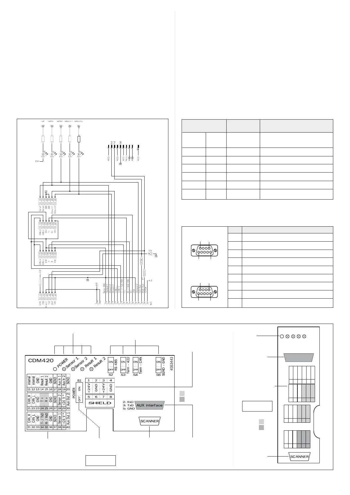
Stromlaufplan Anschlusskarte 2 (ID-Sensor 2)
Circuit diagram of connecting board 2 (ID sensor 2)
Aufbau, Klemmenbelegung/design, terminal assignment
Interne Verbindungsleitungen
Internal connecting cables
Anschlusskarte 1 Anschlusskarte 2
Connecting board 1 Connecting board 2
Anschluss- Signal Aderfarbe Anschlussklemme
klemme
Terminal Wire color Terminal
21 CAN_H Weiss/White 61
22 CAN_L Blau/Blue 62
3 V
s
Rot/Red 71
4 GND
Schwarz/Black 72
8 Shield Grau/Grey 73
Anschluss PC
PC connection
Anschluss
ID-Sensor
ID sensor
connection
LEDs
Klemmleisten
ID-Sensor
Terminal strips
for ID sensor
CDM420-0004S01:
Pinbelegung der 9-pol. D-Sub-Dosen auf Frontblende
Pin assignment of 9-pin D-Sub female connectors on front
Pin Signal
1 Not connected
2 TxD (RS 232), AUX
3 RxD (RS 232), AUX
4 Not connected
5 GND
6 Not connected
7 Not connected
8 Not connected
9 Not connected
(ID Sensor 1)
(ID Sensor 2)
Kongurationsschalter
Conguration switches
Anschluss ID-Sensor
ID sensor connection
Klemmleisten
ID-Sensor
Terminal strips for
ID sensor
Anschluss PC
PC connection
Kongurationsschalter
Conguration switches
Klemmleisten für Versor-
gungsspannung
Terminal strips for power
supply voltage
LEDs
ID sensor 1
51 52 53 54 55 56
CAN_H
CAN_L
GND
T+
GND
R+
41 42 43 44 45 46
Sens 1
Sens 2
GND
GND
Result 2
Result 1
71 72 73 74 75 76
+24 V
GND
Shield
TxD
GND
RxD
61 62 63 64 65 66
CAN_H
CAN_L
GND
T– / TxD
GND
R– / RxD
AUX interface
Power
Sens 1
Sens 2
Res 2
Res 1
HOST
AUX
HOST
AUX
ID sensor 2