6 Mounting
DANGER
H
azard due to lack of effectiveness of the protective device
Persons and parts of the body to be protected may not be recognized in case of non-
observance.
b
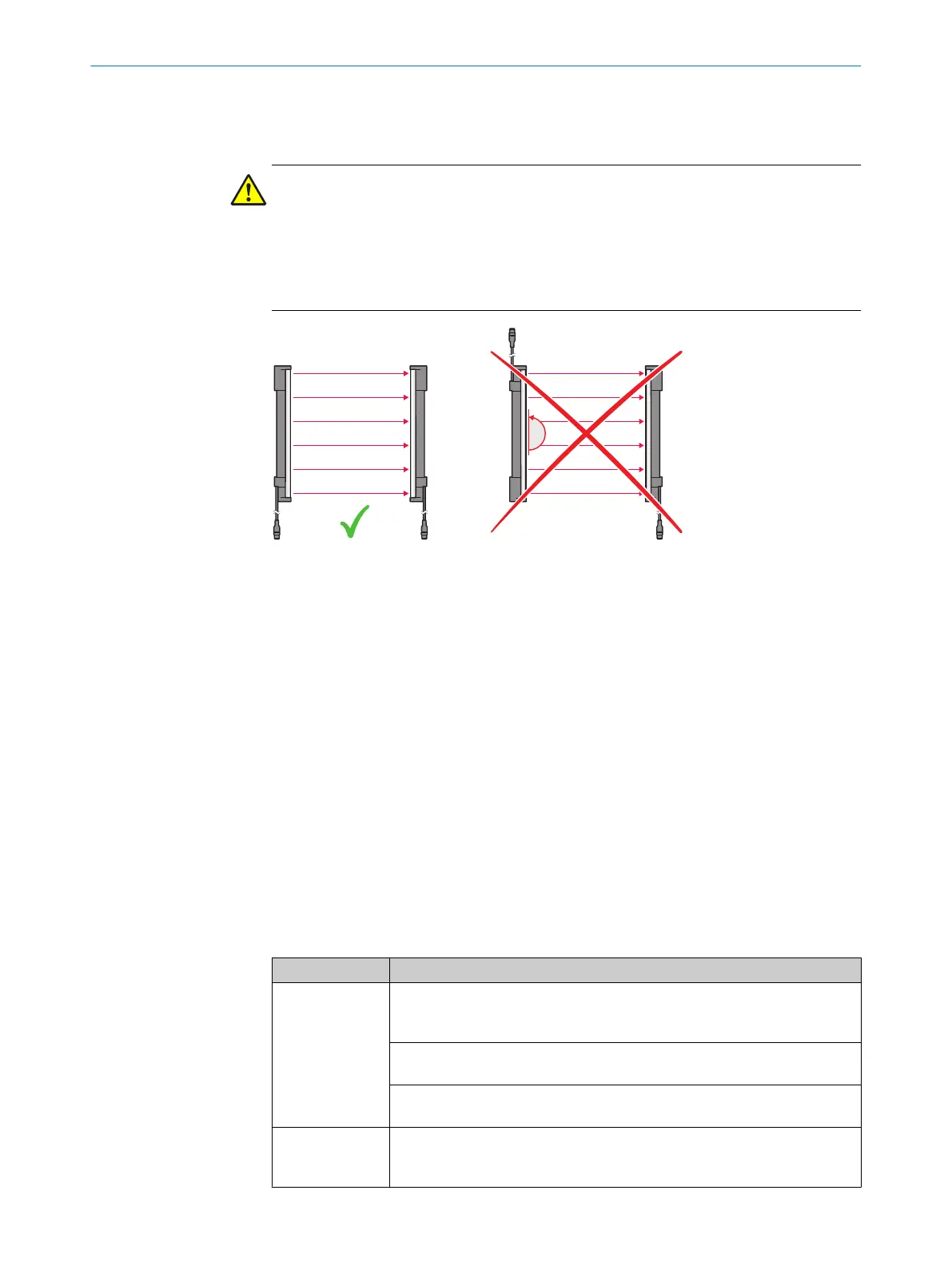
The end with the cable connection must point in the same direction for the sender
and receiver.
b
Mount t
he sender and receiver on a level surface.
b
Mount the sender and receiver such that a right-angled protective field is estab‐
lished, i.e. when mounted vertically at the same height. For minor adjustments
when aligning, the sender and receiver can be adjusted longitudinally in the brack‐
ets.
b
Position the brackets near the ends of the housing. For devices with a protective
field height > 300 mm, the distance between the bracket and the end of the hous‐
ing must not exceed 1/4 of the length of the housing. If the device is exposed to
strong vibrations during operation, mount the top bracket at a height where the
offset in the safety light curtain housing rests on the bracket.
b
Tightening torque for the screws used to mount the bracket: 5 Nm to 6 Nm. Tight‐
ening torque for the screws used to secure the safety light curtain in the bracket:
2.5 Nm to 3 Nm. Higher torques can damage the bracket, while lower torques are
not secure enough to prevent the safety light curtain from moving.
b
Make sure that the sender and receiver are aligned correctly. The optical lens sys‐
tems of the sender and the receiver must be located opposite one another.
b
If necessary, use a spirit level to check that the components are parallel.
6.1 Mounting the QuickFix bracket
Lateral and rear mounting with the QuickFix bracket
Mounting type Description
On the side Fasten the M5 screw to the machine or profile frame through the QuickFix
br
acket. A screw nut or threaded hole is required on the machine or profile
frame (!).
Fasten the M5 screw to the QuickFix bracket through the machine or profile
fr
ame. A screw nut is required for each QuickFix bracket ( ").
Fasten the M5 screw to the profile frame through the QuickFix bracket. A
slidin
g nut is required on the profile frame (§).
On the back Fasten the M5 screw to the machine or profile frame through the QuickFix
br
acket. A screw nut or threaded hole is required on the machine or profile
frame ($).
MOUNTING INSTRUCTIONS
14
M O U N T I N G I N S T R U C T I O N S | deTec4 8022020/ZYO3/2018-05-15 | SICK
Subject to change without notice