Mounting: D
6.2 Mounting the FlexFix bracket
Lateral and rear mounting with the FlexFix bracket
Mounting type Description
On the side With the M5 screw through the FlexFix bracket on the machine or profile
frame. A screw nut or threaded hole is required on the machine or profile
frame (!).
With the M5 screw through the FlexFix bracket on the profile frame. Two slid‐
in
g nuts are required on the profile frame (").
On the back With the M5 screw through the FlexFix bracket on the machine or profile
fr
ame. A screw nut or threaded hole is required on the machine or profile
frame (§).
1. After mounting the FlexFix brackets, screw the sender and receiver into the FlexFix
br
ackets from the front and align the sender and receiver.
NOTE
T
he safety light curtain can only be screwed in when both FlexFix brackets are in align‐
ment.
Recommendation:
1. Only hand-tighten the screws on the FlexFix brackets at first.
2. Align the two FlexFix brackets. To do this, place a straightedge or spirit level, for
example, at the screw mounting surfaces of the FlexFix brackets that are not being
used.
3. Tighten the screws.
2. Use an M5 screw to fix the position of the sender and receiver in the FlexFix
br
acket.
Mounting:
E
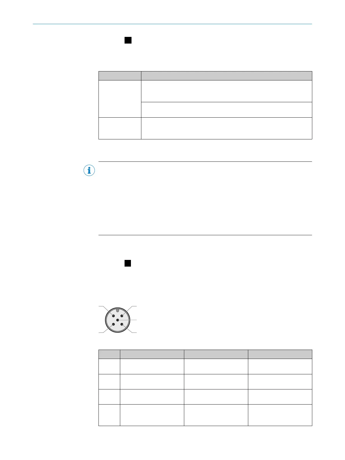
7 Pin assignment
System connection (M12, 5-pin)
System connection pin assignment (male connector, M12, 5-pin)
Pin Wire color
1)
s S
ender r Receiver
1 Brown +24 V DC (voltage supply
in
put)
+24 V DC (voltage supply
input)
2 White In2 (laser alignment aid
button)
OSSD1
3 Blue 0 V DC (voltage supply
input)
0 V DC (voltage supply
input)
4 Black In1 (laser alignment aid
s
witch/cascade synchro‐
nization input)
OSSD2
MOUNTING INSTRUCTIONS
8022020/ZYO3/2018-05-15 | SICK M O U N T I N G I N S T R U C T I O N S | deTec4
15
Subject to change without notice
 Loading...


