Home
SICK
Outdoor Light
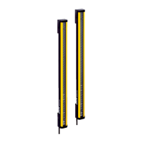
deTec4 Core
SICK deTec4 Core User Manual
4
of 1
of 1 rating
80 pages
Give review
Manual
Specs
To Next Page
To Next Page
O
P
E
R
A
T
I
N
G
I
N
S
T
R
U
C
T
I
O
N
S
deT
ec4 Core
Saf
ety light cur
tain
2
Table of Contents
Table of Contents
3
1 About this Document
6
Scope
6
Target Groups and Structure of These Operating Instructions
6
Additional Information
7
Symbols and Document Conventions
7
2 Safety Information
9
General Safety Notes
9
Correct Use
9
Requirements for the Qualification of Personnel
10
3 Product Description
11
Structure and Function
11
Sender and Receiver
11
Product Characteristics
12
Absence of Blind Zones
12
Automatic Calibration of the Protective Field Width
12
Status Indicators
12
Sender Indicators
13
Receiver Indicators
14
Example Applications
15
Hazardous Point Protection
15
Access Protection
15
Hazardous Area Protection
16
4 Project Planning
17
Manufacturer of the Machine
17
Operator of the Machine
17
Design
17
Scanning Range and Protective Field Width
18
Minimum Distance from the Hazardous Point
18
Protective Field
20
Minimum Distance to Reflective Surfaces
21
Representation of the Accessibility of Electro-Sensitive Protective Device by Reach- Ing Over. Left: Protective Field that Cannot be Reached Over. Right: Protective Field that Can be Reached over
21
Minimum Distance from Reflective Surfaces
21
Protection against Interference from Systems in Close Proximity to each Other
22
Graph of Minimum Distance from Reflective Surfaces
22
Preventing Mutual Interference from System 1 and System 2
22
Formula for Calculating the Minimum Distance from Reflective Surfaces
22
Integration in Electrical Control
23
Trouble-Free Operation Due to Reversed Direction of Transmission of System 1 and System 2
23
Dual-Channel and Isolated Connection of OSSD1 and OSSD2
24
No Potential Difference between Load and Protective Device
24
Restart Interlock
25
Schematic Representation of Operation with Restart Interlock
25
External Device Monitoring (EDM)
26
Connection Diagrams
26
Connection Diagram for UE48-2OS with Restart Interlock and External Device Moni- Toring
26
Testing Plan
27
Test Rod Check
28
Visual Check of the Machine and the Protective Device
29
Test Rod Check: Step 1
29
Test Rod Check: Step 2
29
5 Mounting
31
Safety
31
Unpacking
31
Installation
32
Sender and Receiver Must Not be Installed at 180° Rotated Relative to each Other
33
Mounting the Quickfix Bracket
34
Lateral and Rear Mounting with the Quickfix Bracket
34
Mounting the Flexfix Bracket
35
Mounting the Quickfix Bracket to a Profile
35
Mount Flexfix Brackets to a Profile Frame
36
Lateral and Rear Mounting with the Flexfix Bracket
36
Inserting the Safety Light Curtain in the Flexfix Brackets
37
Mounting the Upgrade Bracket
38
Upgrade Bracket, Installation Version a
39
Upgrade Bracket, Installation Version B
39
Upgrade Bracket, Installation Version C
40
6 Electrical Installation
41
Safety
41
System Connection (M12, 5-Pin)
42
Dual-Channel and Isolated Connection of OSSD1 and OSSD2
42
No Potential Difference between Load and Protective Device
42
System Connection Via Connection Cable (M12, 5-Pin to 8-Pin)
43
System Connection Pin Assignment (M12, 5-Pin)
43
7 Commissioning
44
Safety
44
Overview
45
Switching on
45
Alignment of the Sender and Receiver
45
Aligning the Sender and Receiver
46
Alignment with the Quickfix Bracket
47
Alignment with the Flexfix Bracket or with the Upgrade Bracket
47
Quickfix Bracket: Adjust Vertically
47
Indication of the Alignment Quality
48
Flexfix Bracket: Adjust Vertically/Rotate
48
Check During Commissioning and Modifications
49
8 Operation
50
Safety
50
Regular Thorough Check
50
9 Maintenance
51
Safety
51
Regular Cleaning
51
Regular Thorough Check
52
10 Troubleshooting
53
Safety
53
Diagnostic Leds
53
Fault Indicators
53
Fault Indicator on the Sender
54
Fault Indicator on the Receiver
54
11 Decommissioning
56
Protection of the Environment
56
Disposal
56
12 Technical Data
57
Data Sheet
57
General System Data
57
Technical Specifications, Sender
57
Technical Specifications, Receiver
58
Operating Data
58
Response Time
59
Power Consumption
59
Response Time Dependent on the Protective Field Height
59
Power Consumption, Sender and Receiver
59
Length of Cable
60
Table of Weights
60
Maximum Lengths of Cable for Wire Cross-Section 0.34 MM 2 , Copper Wire
60
Weight of Sender and Receiver
60
Dimensional Drawings
61
Dimensional Drawing, Sender and Receiver
61
Dimensions Based on the Protective Field Height, Sender and Receiver
61
13 Ordering Information
63
Scope of Delivery
63
Ordering Information Detec4 Core
63
Ordering Information Detec4 Core, Resolution 14 MM
63
Ordering Information Detec4 Core, Resolution 30 MM
63
14 Accessories
64
Brackets
64
Dimensional Drawing of the Quickfix Bracket (2066048)
64
Brackets Ordering Information
64
Dimensional Drawing of the Flexfix Bracket (2066614)
65
Mounting Accessories
66
Dimensional Drawing of the Upgrade Bracket (2071021)
66
Mounting Accessories Ordering Information
66
Weld Spark Guard
67
Connectors
67
Mounting the Weld Spark Guard
67
Weld Spark Guard Ordering Information
67
Ordering Information for M12 Connecting Cable, 5-Pin (0.34 MM 2 )
67
Alignment Aid
68
Deflector Mirrors
68
Function and Use
68
Ordering Information, Connection Cable (Replacement of Existing Devices)
68
Distributor Ordering Information
68
Resistance Terminal Ordering Information
68
Ordering Information for Power Supply
68
Alignment Aid Ordering Information
68
Mounting
69
Change in Scanning Range Using Deflector Mirrors
69
Example of Use of Deflector Mirrors
69
Deflector Mirror PNS75 - Ordering Information
70
Deflector Mirror PSN125 - Ordering Information
70
Maximum Distance When Using Deflector Mirrors
70
Scanning Range with and Without 1 or 2 Deflector Mirrors
70
Ordering Information, Deflector Mirror PNS75
70
Ordering Information, Deflector Mirror PSN125
70
Mirror Columns and Device Columns
71
Mirror Columns
71
Device Columns
71
Cleaning Agent
71
Ordering Information for Mirror Columns
71
Ordering Information for Device Columns
71
Cleaning Agent Ordering Information
71
Test Rods
72
Ordering Information, Test Rods
72
15 Annex
73
Compliance with EU Directives
73
Note on Specified Standards
74
Checklist for Initial Commissioning and Commissioning
75
16 List of Figures
76
17 List of Tables
77
4
Based on 1 rating
Ask a question
Give review
Questions and Answers:
Need help?
Do you have a question about the SICK deTec4 Core and is the answer not in the manual?
Ask a question
SICK deTec4 Core Specifications
General
Enclosure rating
IP65, IP67
Operating voltage
24 V DC
Resolution
14 mm
Supply voltage Uv
24 V DC
Light source
Infrared LED
Connection type
M12 connector