The dangerous state of the machine 1 is br
ought to an end if the light path is inter‐
rupted 2 and is not re-enabled 3 until the operator presses the reset pushbutton
located outside the hazardous area 4. The machine can then be restarted.
Depending on the applicable national regulations, there must be a restart interlock if a
person can stand behind the protective field. Observe IEC 60204-1.
4.4.2 External device monitoring (EDM)
Overview
T
he external switching elements (external device monitoring, EDM) must be inspected
in line with the regulations which apply at the place of installation or the required relia‐
bility of the safety function.
The external device monitoring (EDM) monitors the status of downstream contactors.
Important information
NOTE
Bec
ause the safety light curtain does not have integrated external device monitoring,
this must be implemented in the external control, if required.
Prerequisites
•
P
ositively guided contactors are used for shutting down the machine.
If the auxiliary contacts of the positively guided contactors are connected to the
external device monitoring, the external device monitoring checks whether the
contactors drop off when the OSSDs are switched off.
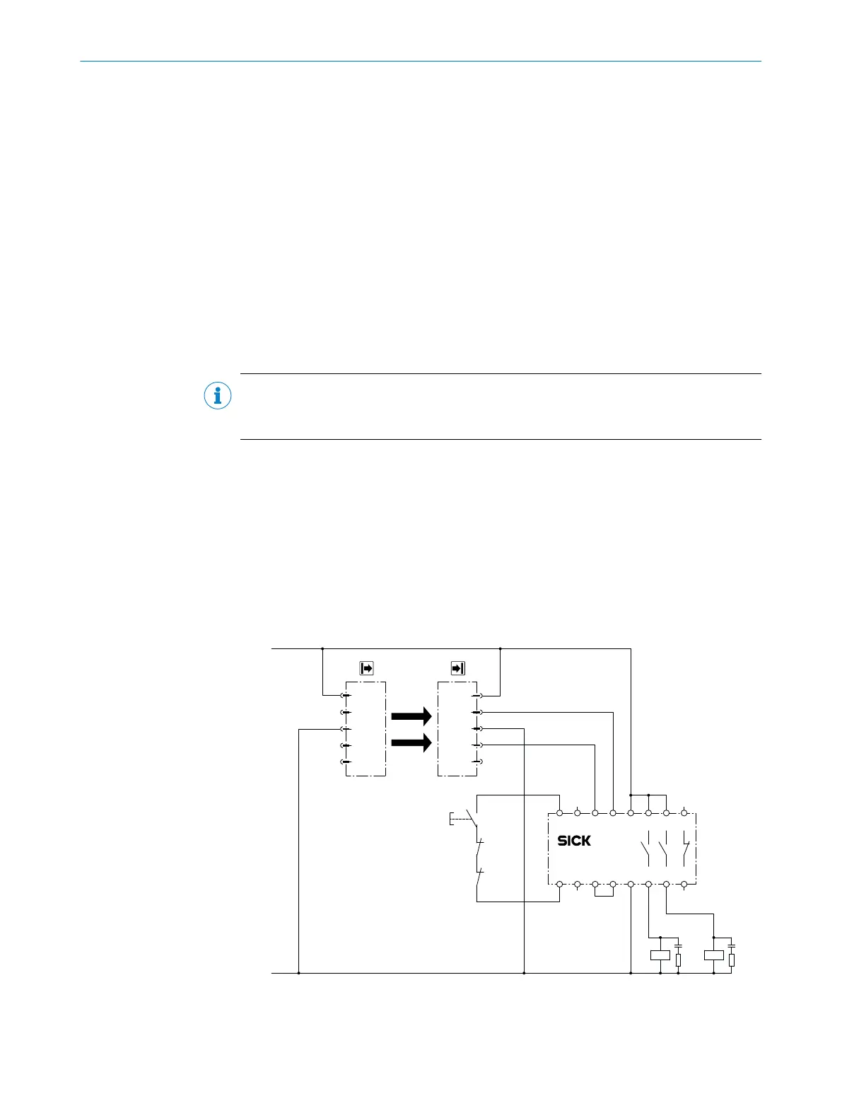
4.4.3 Connection diagrams
Connection diagram for UE48-2OS with restart interlock and external device monitor‐
in
g
S34 S21S35 S22
S33 S12S11 S31
14A2 24 32
13A1 23 31
UE48-2OS2D2
K1 K2
S1
K1
K2
OSSD1
OSSD2
n.c.
GND
+24V
1
2
3
4
5
+24V
n.c.
GND
n.c.
n.c.
1
2
3
4
5
24 VDC
0 VDC
Figure 16: Connection diagram for UE48-2OS with restart interlock and external device monitor‐
in
g
4 P
ROJECT PLANNING
26
O P E R A T I N G I N S T R U C T I O N S | deTec4 Core 8014253/ZOH3/2017-08-04 | SICK
Subject to change without notice