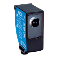
Example: Isolated connection of OSSD1 and OSSD2
Figure 26: Dual-channel and isolated connection of OSSD1 and OSSD2
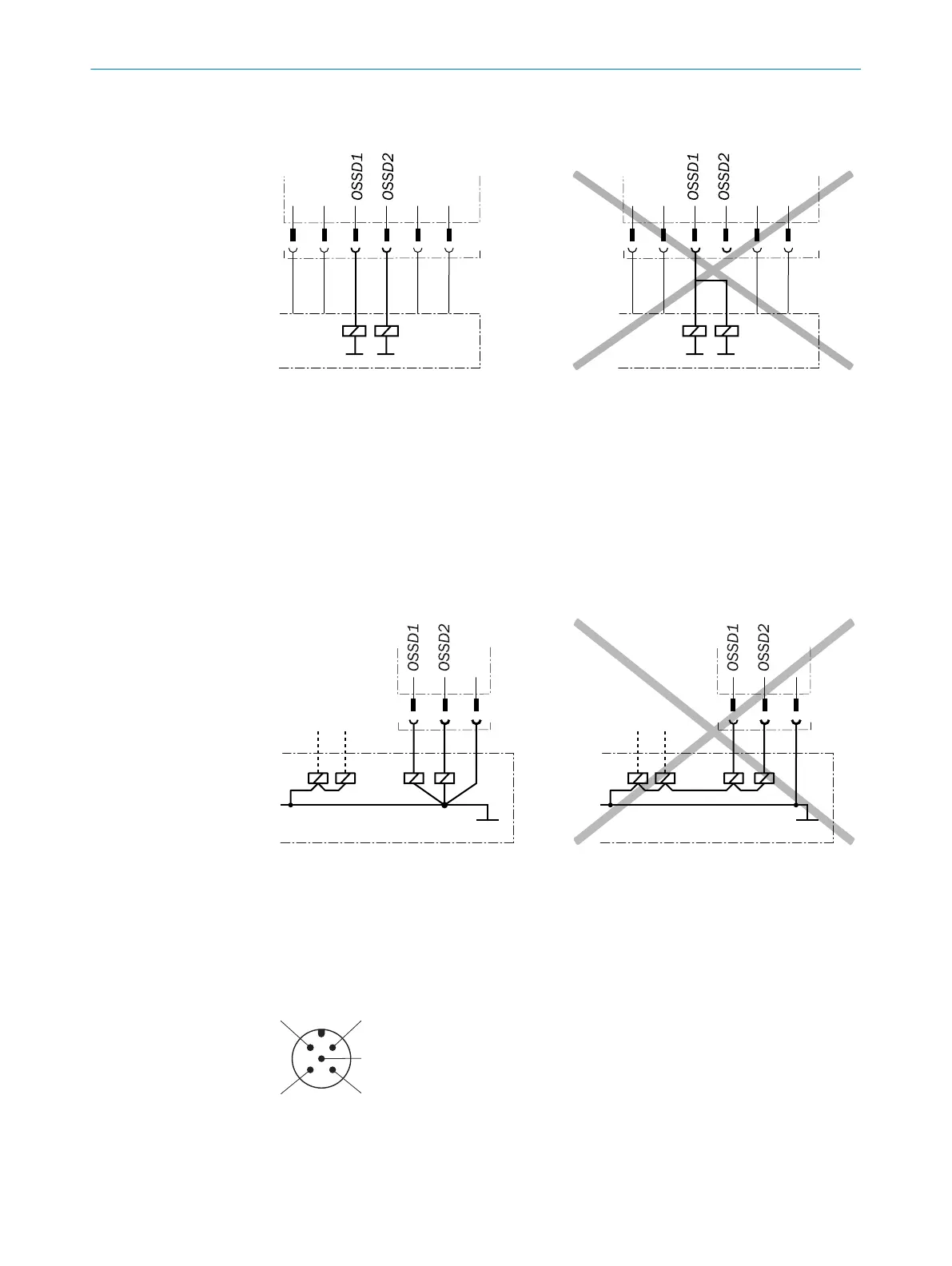
Avoiding any potential difference between load and protective device
•
If y
ou connect loads to the output signal switching devices (safety outputs) that
then also switch if controlled with negative voltage (e.g., electro-mechanical con‐
tactor without reverse polarity protection diode), you must connect the 0 V connec‐
tions of these loads and those of the corresponding protective device individually
and directly to the same 0 V terminal strip. In the event of a fault, this is the only
way to ensure that there can be no potential difference between the 0 V connec‐
tions of the loads and those of the corresponding protective device.
Figure 27: No potential difference between load and protective device
Further topics
•
"Int
egration in electrical control", page 23
6.2 System connection (M12, 5-pin)
Figure 28: System connection (M12, 5-pin)
6 ELECTRICAL INSTALLATION
42
O P E R A T I N G I N S T R U C T I O N S | deTec4 Core 8014253/ZOH3/2017-08-04 | SICK
Subject to change without notice