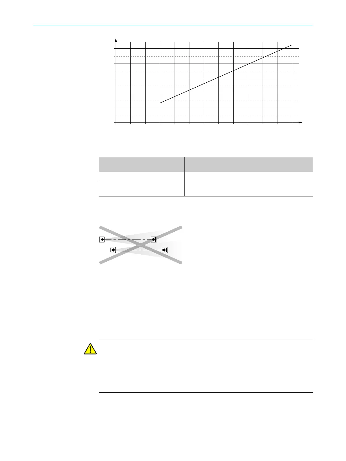
500
400
300
200
100
a/mm
1 2 3 4 5 6 7 8 9 10 11 12 D/m
Figure 10: Graph of minimum distance from reflective surfaces
T
able 1: Formula for calculating the minimum distance from reflective surfaces
Distance D between sender and
r
eceiver in m
Calculation of the minimum distance (a) from reflective
surfaces in mm
D ≤ 3 m a = 131 mm
D > 3 m a = tan (2.5°) × 1,000 mm/m × D = 43.66 × 1 mm/m ×
D
4.3.4 Protection against interference from systems in close proximity to each other
Overview
Figure 11: Preventing mutual interference from system
1
and system
2
The infrared light beams of the sender of system 1 can interfere with the receiver of
system 2. This can disrupt the protective function of system 2. This would mean that
the operator is at risk.
Avoid such installation situations or take appropriate action, e.g., install optically opa‐
que partitions or reverse the direction of transmission of a system.
Important information
DANGER
H
azard due to lack of effectiveness of the protective device
Systems of safety light curtains that operate in close proximity to each other can inter‐
fere with each other.
b
Use appropriate measures to prevent systems in close proximity from interfering
with each other.
4 PROJECT PLANNING
22
O P E R A T I N G I N S T R U C T I O N S | deTec4 Core 8014253/ZOH3/2017-08-04 | SICK
Subject to change without notice