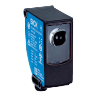
Receiver indicators
Resolution 30 mmResolution 14 mm
ERR
OSSD
ERR
OSSD
1 2 3 4
1 2 3 4
2
1
3
Figure 3: Receiver indicators
S
ix light emitting diodes on the receiver indicate the operational status:
Position LED color Indication Labeling
1
Red/green OSSD status OSSD
2
Red Fault indicator ERR
3
Blue Alignment quality 1, 2, 3, 4
The blue alignment quality LEDs in combination with the red flashing ERR LED also
deno
te fault indications.
Complete overview of the LED statuses and their meanings: see "Diagnostic LEDs",
page 53.
3 P
RODUCT DESCRIPTION
14
O P E R A T I N G I N S T R U C T I O N S | deTec4 Core 8014253/ZOH3/2017-08-04 | SICK
Subject to change without notice