Minimum Typical Maximum
Shock resistance
5)
10 g, 16 ms (IEC 60068-2-27)
1)
Maximum permissible conductor resistances must be observed.
2)
The temperature difference between sender and receiver must not exceed 25 K.
3)
The cable belonging to the device incl. the associated connection plug must not be flexibly mounted
under –25° C
.
4)
Test conditions per axis: 1 octave/minute, amplitude: 0.35 mm, 20 sweeps.
5)
Test conditions per axis: 500 shocks.
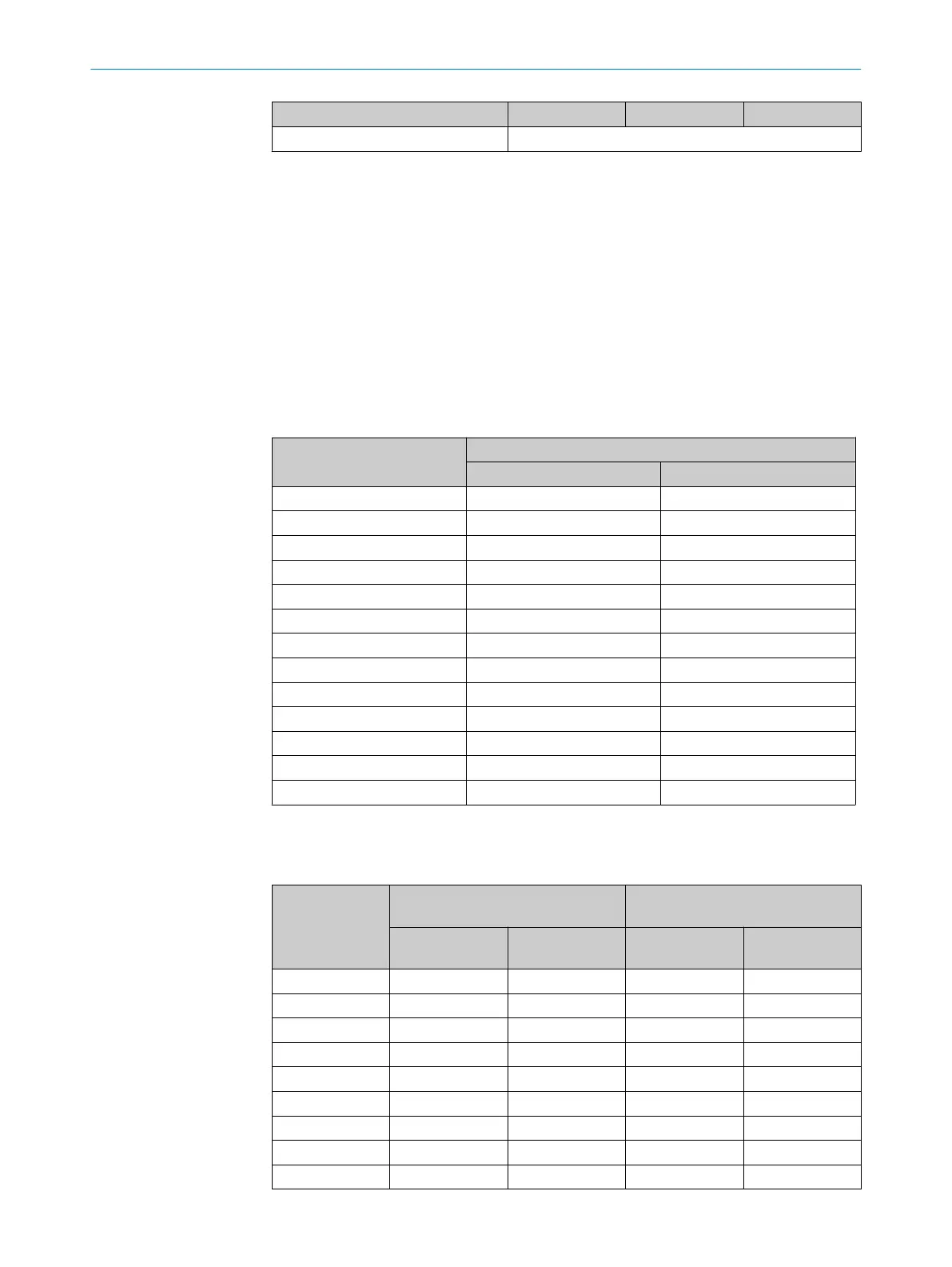
12.2 Response time
Overview
T
he response time is subject to the following parameters:
•
Resolution
•
Protective field height
Table 12: Response time dependent on the protective field height
Protective field height in mm Response time in ms
Resolution 14 mm Resolution 30 mm
300 11 10
450 12 10
600 13 10
750 13 11
900 14 11
1050 15 11
1200 16 12
1350 17 12
1500 18 13
1650 19 13
1800 20 13
1950 21 14
2100 22 14
12.3 Power consumption
Table 13: Power consumption, sender and receiver
Protective field
hei
ght in mm
Typical power consumption of
sender in W
Typical power consumption of
receiver in W
1)
Resolution
14 mm
Resolution
30 mm
Resolution
14 mm
Resolution
30 mm
300 0.96 0.82 1.92 1.63
450 1.08 0.86 2.16 1.73
600 1.20 0.91 2.40 1.82
750 1.32 0.96 2.64 1.92
900 1.44 1.01 2.88 2.02
1050 1.56 1.06 3.12 2.11
1200 1.68 1.10 3.36 2.21
1350 1.80 1.15 3.60 2.30
1500 1.92 1.20 3.84 2.40
TECHNICAL DATA 12
8014253/ZOH3/2017-08-04 | SICK O P E R A T I N G I N S T R U C T I O N S | deTec4 Core
59
Subject to change without notice