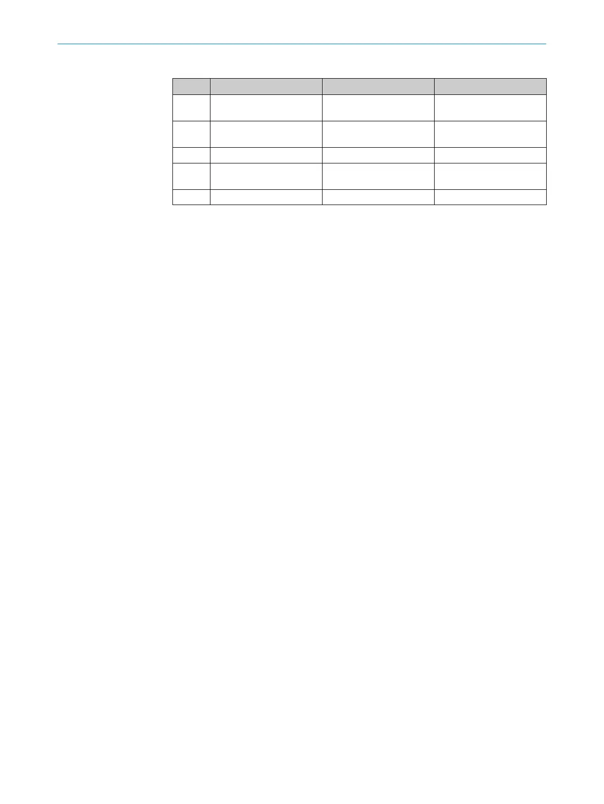
Table 4: System connection pin assignment (M12, 5-pin)
Pin Wire color
s S
ender r Receiver
1 Brown +24 V DC (
power supply
input)
+24 V DC (power supply
input)
2 White Reserved OSSD1 (output signal
switching device 1)
3 Blue 0 V DC (power supply input) 0 V DC (power supply input)
4 Black Reserved OSSD2 (output signal
switching device 2)
5 Gray Not yet assigned Not yet assigned
Connection diagram for the electrical installation: see "Int
egration in electrical control",
page 23.
6.3 System connection via connection cable (M12, 5-pin to 8-pin)
An optional connection cable is available to connect the 5-pin system connection to an
e
xisting 8-pin female connector. The connection cable can be used to replace an exist‐
ing C4000 safety light curtain with a deTec4 Core, without having to route new cables.
ELECTRICAL INSTALLATION 6
8014253/ZOH3/2017-08-04 | SICK O P E R A T I N G I N S T R U C T I O N S | deTec4 Core
43
Subject to change without notice