Approach
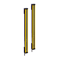
Figure 19: Sender and receiver must not be installed at 180° rotated relative to each other
b
Mount t
he sender and receiver on a level surface.
b
Mount the sender and receiver such that a right-angled protective field is estab‐
lished, i.e., when mounted vertically at the same height. For minor adjustments
when aligning, the sender and receiver can be adjusted longitudinally in the brack‐
ets.
b
If possible, select the mounting height of the top bracket such that the offset in
the safety light curtain housing is resting on the bracket. This prevents the safety
light curtain from sliding down during mounting.
b
Tightening torque for the screws used to mount the bracket: 5 Nm … 6 Nm. Tight‐
ening torque for the screws used to secure the safety light curtain in the bracket:
2.5 Nm … 3 Nm. Higher torques can damage the bracket while lower torques do
not provide adequate fixation to prevent the safety light curtain from moving.
b
Make sure that the sender and receiver are aligned correctly. The optical lens sys‐
tems of the sender and the receiver must be located opposite one another.
b
If necessary, use a spirit level to check that the components are parallel.
NOTE
W
hen mounting the brackets, take into account that the brackets can not be mounted
at the same height if different system connectors are used on the sender and receiver.
Further topics
•
"Minimum dis
tance from the hazardous point", page 18
•
"Minimum distance to reflective surfaces", page 21
•
"Alignment of the sender and receiver", page 45
•
"Alignment with the QuickFix bracket", page 47
•
"Alignment with the FlexFix bracket or with the upgrade bracket", page 47
MOUNTING 5
8014253/ZOH3/2017-08-04 | SICK O P E R A T I N G I N S T R U C T I O N S | deTec4 Core
33
Subject to change without notice

 Loading...