Table 28: Scanning range with and without 1 or 2 deflector mirrors
Model name Resolution Scanning
ran
ge, typi‐
cal
1)
Scanning range with
1 deflector mirror, typi‐
cal
1)
Scanning range with
2 deflector mirrors, typi‐
cal
1)
PNS75, PNS125 14 mm 8 m 7.2 m 6.4 m
PNS75, PNS125 30 mm 12 m 10.7 m 9.6 m
1)
If the protective fields are very wide, there is a possibility that all four alignment quality LEDs will not light
up e
ven when alignment is good.
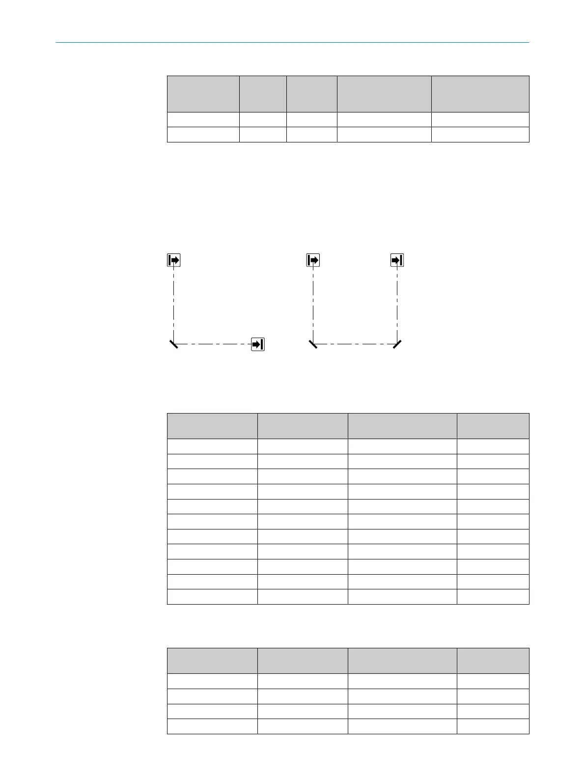
Example: Maximum distance when using deflector mirrors
Ma
ximum distance D between sender or receiver and mirrors or between 2 mirrors
(example applies to 90° beam deflection per mirror, protective field height 900 mm).
•
PNS75: D ≤ 4 m
•
PNS125: D ≤ 8 m
Figure 37: Maximum distance when using deflector mirrors
14.6.4 Deflector mirror PNS75 - ordering information
Table 29: Ordering information, deflector mirror PNS75
Mirror length in mm Max. protective field
hei
ght in mm
Type code Part number
340 300 PNS75-034 1019414
490 450 PNS75-049 1019415
640 600 PNS75-064 1019416
790 750 PNS75-079 1019417
940 900 PNS75-094 1019418
1090 1050 PNS75-109 1019419
1240 1200 PNS75-124 1019420
1390 1350 PNS75-139 1019421
1540 1500 PNS75-154 1019422
1690 1650 PNS75-169 1019423
1840 1800 PNS75-184 1019424
14.6.5 Deflector mirror PSN125 - ordering information
Table 30: Ordering information, deflector mirror PSN125
Mirror length in mm Max. protective field
hei
ght in mm
Type code Part number
340 300 PNS125-034 1019425
490 450 PNS125-049 1019426
640 600 PNS125-064 1019427
790 750 PNS125-079 1019428
14 ACCESSORIES
70
O P E R A T I N G I N S T R U C T I O N S | deTec4 Core 8014253/ZOH3/2017-08-04 | SICK
Subject to change without notice