SP2 system plug extension connection pin assignment (M12 female connector, 5-pin)
Pin Wire color
1)
r R
eceiver
1 Brown 24 V Out (voltage supply
output)
2)
2 White In1
(S
ingle system: EDM [EDM
input]
3)
/ muting signal 1
Host: OSSD input)
3 Blue 0 V Out (voltage supply out‐
put)
4 Black In2
(S
ingle system: RES [reset
pushbutton input] / muting
signal 2
Host: OSSD input)
5 Gray Com2
(S
ingle system: ADO [appli‐
cation diagnostic output] /
IO-Link
Host: cascade communica‐
tion)
1)
Applies to the extension cables recommended as accessories.
2)
Only for cascading deTec devices, not suitable for connecting other devices.
3)
When muting is configured, EDM is not possible at the extension connection.
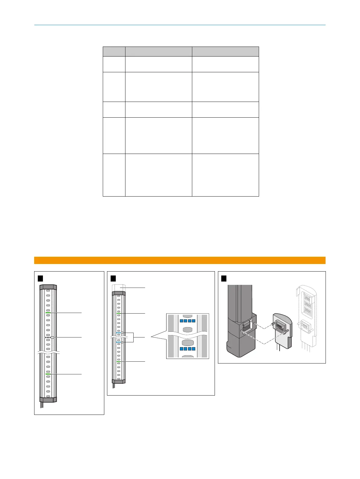
b
F
or cascading: connect the extension connection of the host to the system con‐
nection of guest 1.
b
For cascading with two guest devices: connect additional extension connection of
guest 1 to the system connection of guest 2.
A
B
C
MOUNTING INSTRUCTIONS
18
M O U N T I N G I N S T R U C T I O N S | deTec4 8022020/ZYO3/2018-05-15 | SICK
Subject to change without notice