16 FLPS Multibarrier · Operating Instructions · 8021769/V1-0/2018-03 · © SICK Engineering GmbH
Product Description
Subject to change without notice
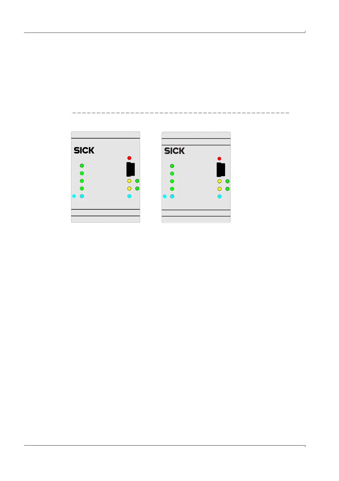
3.5 Displays
● LED –“red” signals an error of the power supply (failure of fuse)
● LED –“blue” for intrinsically safe supply of the flow meter
● LED –“blue” for intrinsically safe supply of the RS485, from the flow meter
● LED –“green” for RS485 TX
● LED –“yellow” for RS485 RX
● x LED –“green” digital outputs
Figure 4 Displays
)O.0
)O.1
DO.3
2b 2a
DO.2
Vcl/Vout
1b 1a
RX2/TX2
RX1/TX1
Vaux
Fus e
failed
FLPS2-60042-S-5
-FI.1+
-+
-FI.0+
2B 2A
-DI.3+
-+
-DI.2+ 1B 1A
-FO.0+-FO.1+
-DO.2+
-DO.3+ 1b 1a
2b 2a
PartNo. 20981
FO.0
DO.3
DO.2
FO.1
2b 2a
Ethernet
RX2/TX2
RX1/TX1
Vaux
Fuse
failed
FLPS2-6004E-S-5
-FI.1+
-FI.0+
-+
2B 2A
-
DI.3+
-DI.2+
-+
1B 1A
-FO.1+
-FO.0+
-DO.3+ -DO.2+
2b 2a
Vcl/Vout
Part No. 2098136
FLPS2-60042-S-5
FLPS2-6004E-S-5