24 FLPS Multibarrier · Operating Instructions · 8021769/V1-0/2018-03 · © SICK Engineering GmbH
Installation
Subject to change without notice
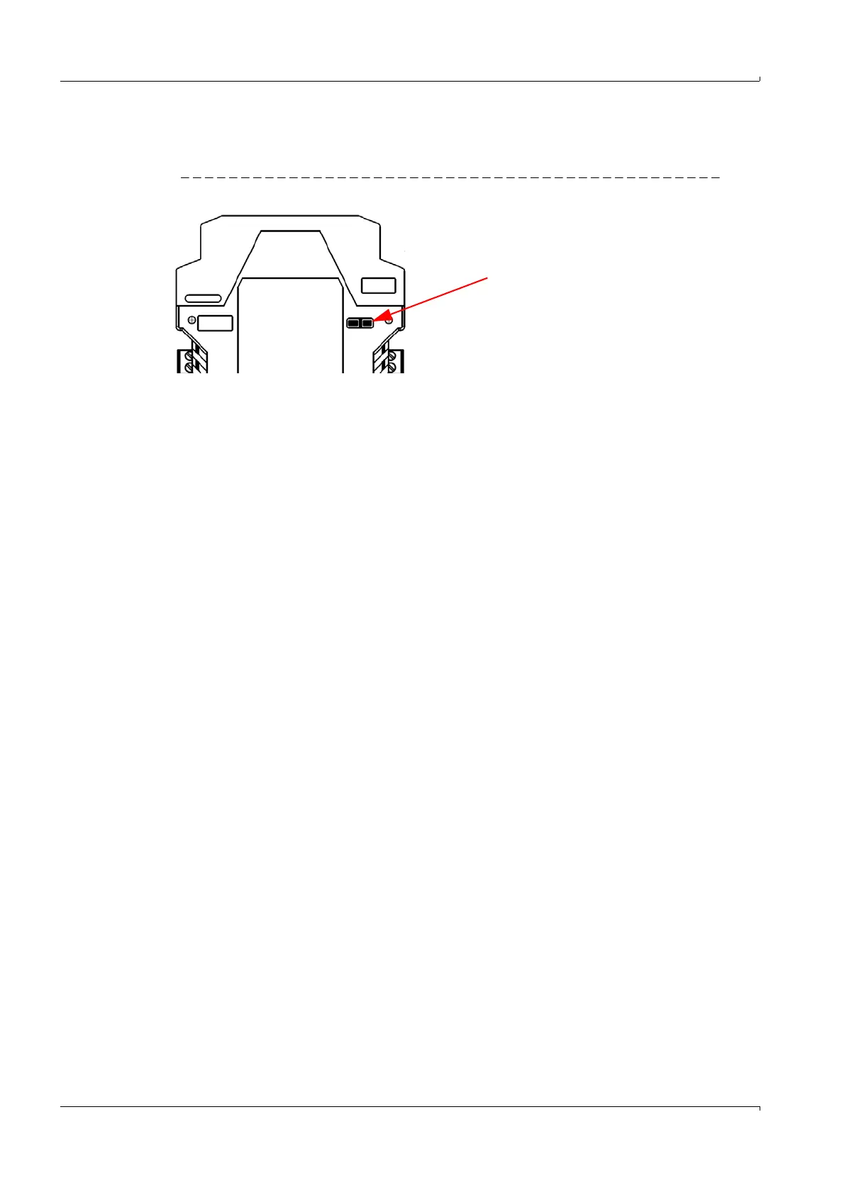
4.3.5 Termination of the RS485 interface
▸
Set the termination to „On“ per default.
Figure 7 DIL switches
4.3.6
Connecting the interfaces
Communication via Modbus TCP
The device version FLPS2-6004E-S-5 is equipped with an Ethernet interface with data pro-
tocol Modbus TCP.
Communication on the serial interface RS485.1 is converted in the FLPS Multibarrier via
the integrated X -Ports from Modbus RTU or Modbus ASCII to Modbus TCP.
Connection is done via an Ethernet cable Cat 5 or higher with a RJ45 plug.
Standard settings
● Standard IP address for Ethernet module: 192.168.0.10
● Standard Subnet mask: 255.255.255.0
● Standard baud rate: 38,400 baud
Service access via USB
Both device versions FLPS2-60042-S-5 and FLPS2-6004E-S-5 are equipped with a mini
USB 2.0 interface.
The serial interface RS485.2 can be used as direct service interface on the FLPS Multibar-
rier by using the mini USB 2.0 interface integrated in the module.
When the serial interface RS485.2 is used and e.g. included in a control system, it will be
disconnected during access via the USB interface. Access via the USB interface has “prior-
ity” in this case.
After deactivation of the connection via the USB interface, activate the connection to the
control system via the serial interface RS485.2 again.