Installation
FLPS Multibarrier · Operating Instructions · 8021769/V 1-0/2018-03 · © SICK Engineering GmbH 27
Subject to change without notice
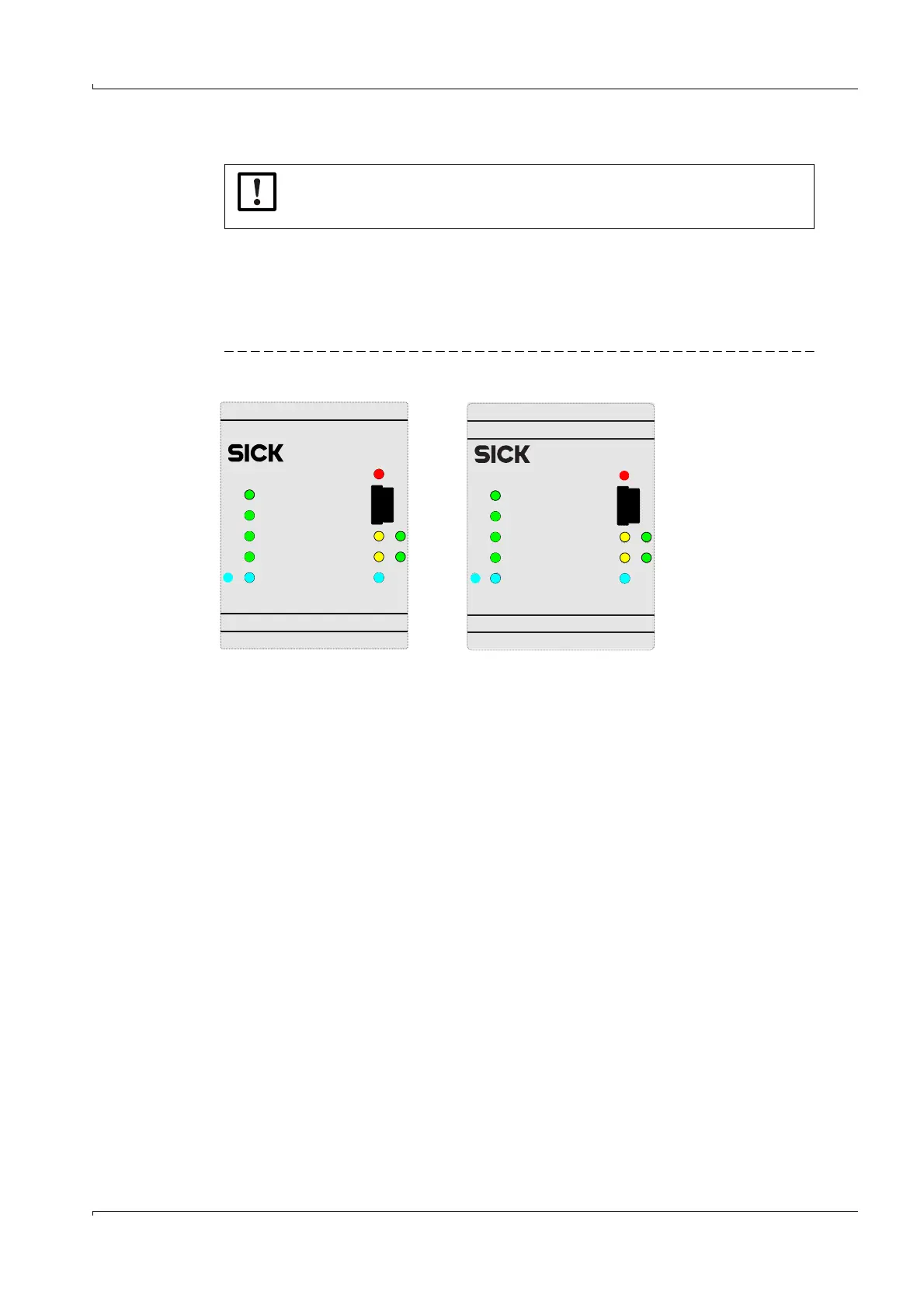
4.4 Function check
After finishing the installation work described in → p. 19, §4.3, switch on the power supply to
the device.
The blue, green and/or yellow LEDs are on and signal the correct power supply of the gas
flow meter.
The red LED “Fuse failed” is off.
Figure 10 Function check
IMPORTANT:
Check for correct wiring and function of the FLPS Multibarrier prior to commis-
sioning.
)O.0
)O.1
DO.3
2b 2a
DO.2
Vcl/Vout
1b 1a
RX2/TX2
RX1/TX1
Vaux
Fus e
failed
FLPS2-60042-S-5
-FI.1+
-+
-FI.0+
2B 2A
-DI.3+
-+
-DI.2+ 1B 1A
-FO.0+-FO.1+
-DO.2+
-DO.3+ 1b 1a
2b 2a
PartNo. 20981
FO.0
DO.3
DO.2
FO.1
2b 2a
Ethernet
RX2/TX2
RX1/TX1
Vaux
Fuse
failed
FLPS2-6004E-S-5
-FI.1+
-FI.0+
-+
2B 2A
-
DI.3+
-DI.2+
-+
1B 1A
-FO.1+
-FO.0+
-DO.3+ -DO.2+
2b 2a
Vcl/Vout
Part No. 2098136
FLPS2-60042-S-5
FLPS2-6004E-S-5