Do you have a question about the SICK CDB650 and is the answer not in the manual?
The CDB650 is a connectivity module designed to integrate SICK identification sensors into a network. It acts as a connection module, providing the necessary interfaces and power supply for the ID sensor, and distributing signals to the cables. This device is suitable for use with various SICK ID sensors, including fixed mount bar code scanner CLV62x to CLV64x (type-dependent), CLV69x, Lector series, and RFID read/write devices.
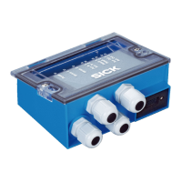
The CDB650 module facilitates the connection of an ID sensor to a host system, such as a PC or a CAN bus. It supports various communication interfaces and provides the necessary power supply for the connected sensor. The module can be expanded with additional storage for ID sensor configuration parameters using an optional CMC600 (Connection Module Cloning) module. It also features an integrated trigger unit for the Lector65x image-based code reader to activate an external illumination unit. The 17-pin M12 male connector is supplied with a plug to maintain an enclosure rating of IP65. An internal 9-pin D-Sub male connector is provided for the serial AUX interface (RS-232) to a computer for configuration and diagnostics. The module includes terminals for serial host interface, CAN bus, switching inputs and switching outputs, trigger unit, voltage supply, and shielding. Visible through the cover are LEDs for displaying active switching inputs and switching outputs, as well as the positions of the configuration switches.
The device's configuration is managed via several switches:
LED indicators provide visual feedback on the device's status:
The CDB650-204 (part no. 1064114) features 11 x LED optical indicators and 1 x 17-pin M12 female connector, A-coded, along with 1 x internal 9-pin D-Sub male connector with spring-loaded terminals. It supports cable glands for 8 or 0.14 mm² to 2.5 mm² wires, and 29 or 0.14 mm² to 1 mm² wires. The supply voltage is 10 V to 30 V DC, compliant with EN 61010 and Class 2 (UL 1310). Power consumption is 1 W, with a maximum input current of 2.4 A. The device includes a MINI blade fuse, 32 V, 2 A. The housing is made of polycarbonate. The trigger unit has a control current of 10 mA. The electrical safety conforms to IEC 61010-1:2010 + Cor.: 2011, and the protection class is III. The enclosure rating is IP65 (EN 60529: A1: 2002-02). EMC resistance is compliant with EN 61000-6-2: 2005-08 and EN 61000-6-3: 2007-01. Vibration resistance is EN 60068-2-6: 2008-02, and shock resistance is EN 60068-2-27: 2009-05. The device weighs approximately 265 g. The ambient temperature for operation ranges from -30 °C to +50 °C, and for storage from -30 °C to +75 °C. The relative air humidity is max. 90 %, non-condensing.
The device supports various data interfaces:
The supply voltage requirements for ID sensors connected to the CDB650 are:
The CDB650 is designed for easy integration into existing systems. It can be mounted and connected to a SICK identification sensor (ID sensor) to a network, peripheral devices, and a voltage supply. The connection module uses a SICK standard cable, and the voltage supply is delivered via cable glands and terminals, with signals distributed on cables.
For commissioning, it is recommended to download connection diagrams from the SICK product documentation website. The supply voltage and type label of the ID sensor should be connected. Mounting, connection, and configuration work must be performed within an ambient temperature range of 0 °C to +50 °C. The device should be used within an ambient temperature range of 0 °C to -40 °C when at rest (no mounting, connection, or configuration work).
Unobstructed access to the internal AUX male connector is required at all times to access the ID sensor via RS-232 for configuration and diagnostics. The maximum length of cable between the connection module and ID sensor when using the serial data interfaces is 10 m. The removable cover with connection diagram can be rotated 180° and locked in the parking position.
The device is supplied with hole and housing dimensions, as well as screw diameter information. For installation and commissioning of the optional CMC600, refer to the CMC600 operating instructions available on the SICK website.
Regular maintenance is crucial for the CDB650's longevity and reliable operation.
Improper cleaning can result in equipment damage. Only use recommended cleaning agents and tools. Never use sharp objects for cleaning. The device must be cleaned regularly from the outside to guarantee heat dissipation and therefore operation. Particular attention must be paid to ensure that the cooling fins and, if present, the fan are free from dust and dirt. Clean using a dry towel or an industrial vacuum cleaner. Do not use cleaning agents.
In case of faults, troubleshooting steps are provided:
For returns, contact SICK Service. The device must be sent in the original packaging or an equivalent padded packaging. To ensure efficient processing and allow for problem identification, include details of the contact person, description of the application, and description of the fault that occurred. Repair work should only be performed by qualified and authorized personnel from SICK AG.
| Brand | SICK |
|---|---|
| Model | CDB650 |
| Category | Control Unit |
| Language | English |