6. Activate the driver for the wired serial host and/or CAN interface in the ID sensor
using the SOPAS ET configuration software (see operating instructions of the ID
sensor).
To do so, use a 3-wire RS-232 data line (null modem line) to connect a computer
to the “AUX” male connector on the connection module, or contact the ID sensor
via Ethernet (depending on the sensor type).
7. Switch on the voltage supply to the connection module.
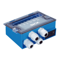
6.5 Terminal assignment
Figure 3: Pin assignment of the terminals and switches
1
LEDs
2
Configuration switch
3
Slot for CMC600
4
PC connection
5
ID sensor connection
6
Terminal strips
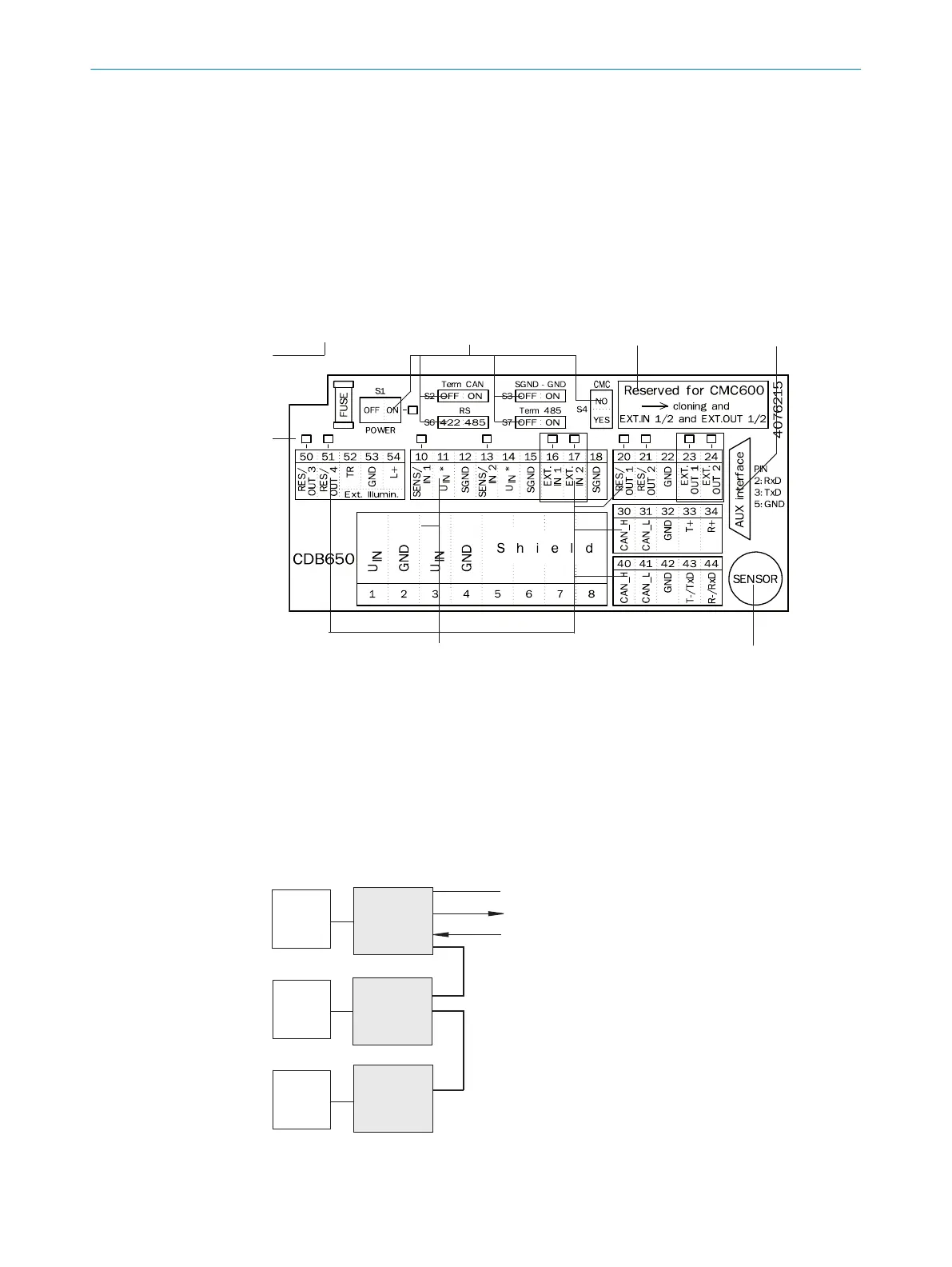
CAN bus
“Host“
“Result 1“
“Sensor 1“
ID sensor
CDB
ID sensor
ID sensor
CDB
CDB
Figure 4: Schematic: Structure of a CAN sensor network
ELECTRICAL INSTALLATION
6
8021689/ZZN2/2021-05-07 | SICK O P E R A T I N G I N S T R U C T I O N S | CDB650
17
Subject to change without notice