3 Product description
•
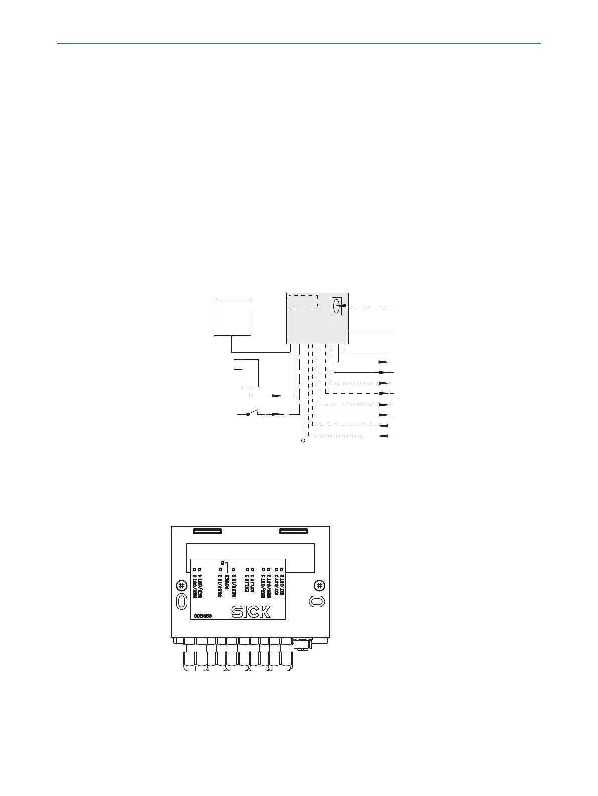
Module for connecting an ID sensor
•
Base module for accommodating an optional CMC600 (Connection Module Clon‐
ing) for external storage of ID sensor configuration parameters. Also used to
activate operating modes as well as to extend the ID sensor by 2 digital switching
inputs and 2 switching outputs (depending on the sensor type).
•
Integrated trigger unit (load switch) for the Lector65x image-based code reader to
activate an external illumination unit that does not have a trigger input
•
17-pin M12 female connector for connecting the ID sensor, supplied with plug to
maintain enclosure rating IP65
•
Internal 9-pin D-Sub male connector, for connecting the serial AUX interface
(RS-232) of the ID sensor to a computer (configuration and diagnostics)
•
Terminals for serial host interface, CAN bus, switching inputs and switching out‐
puts, trigger unit, voltage supply, shielding
•
Visible through the cover: LEDs for displaying active switching inputs and switching
outputs as well as the positions of the configuration switches
“SENS/IN2”
“Host”
DC 10 V ... 30 V
“SENS/IN 1”
“RES/OUT 1”
“Aux”
PC
HOST
SPS/PLC
ID
Sensor
CDB650
. . . .
. . . . .
“CAN”
CAN bus
“RES/OUT 2”
SPS/PLC
CMC600
“EXT. OUT 1”
“EXT. OUT 2”
“EXT. IN 1”
“EXT. IN 2”
“RES/OUT 3”
“RES/OUT 4”
SPS/PLC
SPS/PLC
1
2
1
Photoelectric sensor (read cycle)
2
Switch
3.1 Configuration elements and displays
1
LED display with label
PRODUCT DESCRIPTION 3
8021689/ZZN2/2021-05-07 | SICK O P E R A T I N G I N S T R U C T I O N S | CDB650
9
Subject to change without notice