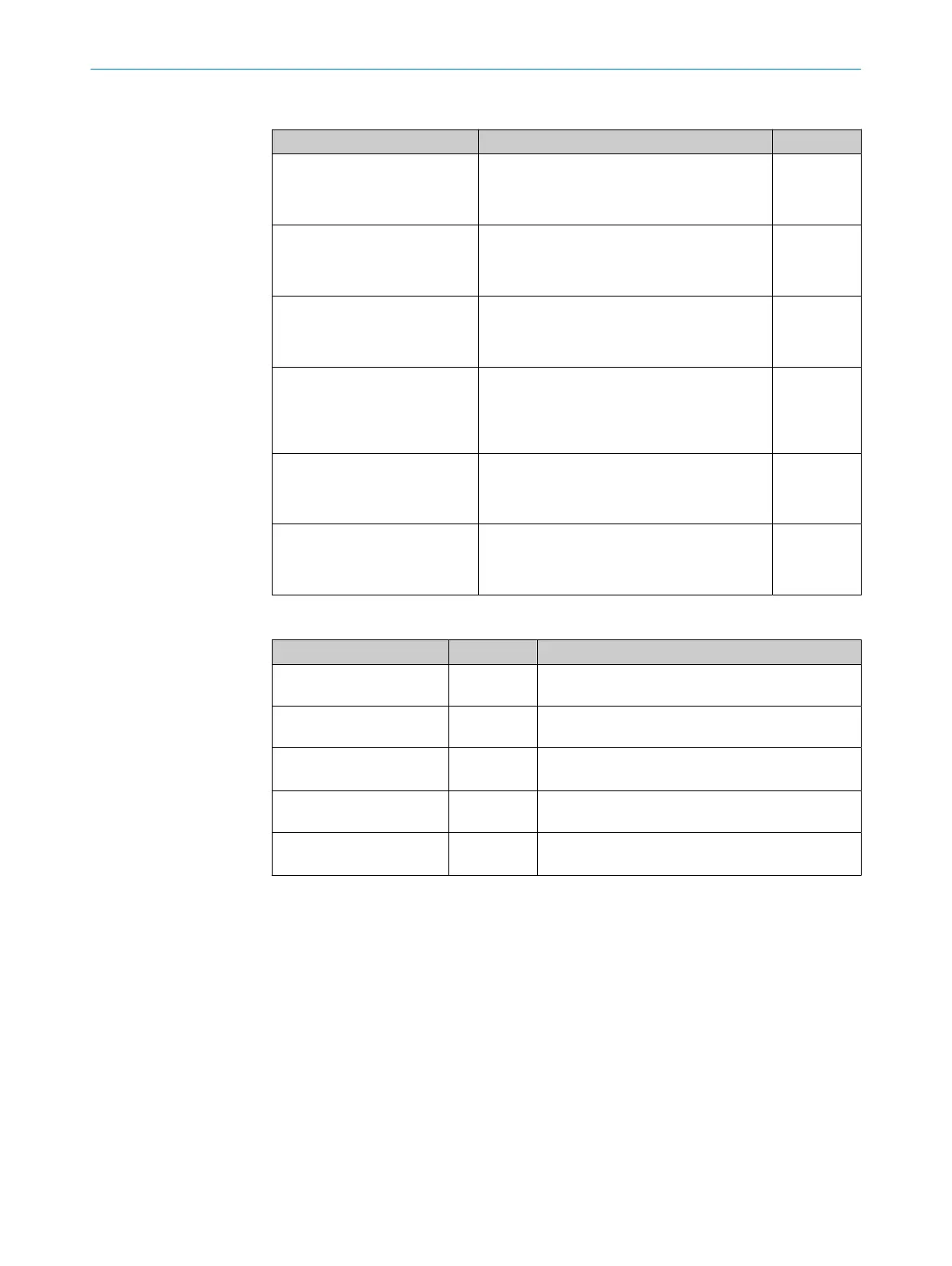
Function of the configuration switches
Switch Function Default
S 1 (Power) Supply voltage applied:
•
ON: Supply voltage on
•
OFF: Supply voltage off
ON
S2 (Term CAN) CAN bus termination:
•
ON: 120 Ohm resistor connected
•
OFF: no termination
OFF
S 3 (SGND-GND) Reference potential for sensor GND:
•
ON: Connected to GND of the ID sensor
•
OFF: Volt-free
OFF
S4 (CMC) Integration of the CMC600:
•
“YES”: CMC600 connected in the cable of
the AUX interface of the ID sensor
•
“NO”: No CMC600 inserted
NO
S 6 (RS422/485) RS-422/485 switching
•
ON: RS-485
•
OFF: RS-422
OFF
S 7 (Term 485) RS-485 termination (receiver)
•
ON: 120 Ohm resistor connected
•
OFF: no termination
OFF
Function of the LEDs
LED Color Function
Power Green Lights up when operating voltage is supplied to the
connection module and switch S 1 is set to “ON”
SENS/IN 1 , SENS/IN 2 Green Lights up when the corresponding input of the ID
sensor is activated
EXT. IN 1
1)
EXT. IN 2
1)
Green Lights up when the corresponding additional input
of the ID sensor (via CMC600) is activated
RES/OUT 1... RES/OUT 4 Orange Lights when the corresponding output of the ID sen‐
sor is present and activated
EXT.OUT 1
1)
EXT.OUT 2
1)
Orange Lights up when the corresponding additional output
of the ID sensor (via CMC600) is activated
1)
The CMC600 module is a prerequisite.
3 PRODUCT DESCRIPTION
10
O P E R A T I N G I N S T R U C T I O N S | CDB650 8021689/ZZN2/2021-05-07 | SICK
Subject to change without notice