6.6 Connecting an external illumination unit for the Lector65x
An external illumination unit with a suitable supply voltage range for the Lector65x can
be connected to the connection module, triggered and activated for this purpose in the
Lector65x as follows
22
GND
21
Res/OUT 2
14
U
IN*
GND
3
U
IN
F
GND
V
S
internal
F
external
LECTOR65x
CDB650 CDB650
Trigger
input
22
GND
21
Res/OUT 2
14
U
IN*
F
internal
Trigger
input
U
IN*
F
external
external
(2 A) (2 A)
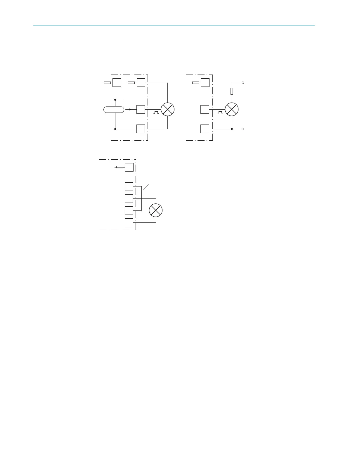
Figure 5: Illumination unit with trigger input
22
GND
52
TR
54
L+
21
Res/OUT 2
14
U
IN*
F
internal
CDB650
(2 A)
1
Figure 6: Illumination unit without trigger input
Connecting an illumination unit with trigger input
The illumination unit (e.g. ICLxxx) must provide flying leads with 3 wires for connection:
•
Supply voltage
•
GND
•
Trigger input
The trigger input of the illumination unit is connected directly to the switching output
Res 2 or Res 4 of the Lector65x in the connection module (see figure 5, page 18). The
illumination unit is supplied either via a separate external voltage V
S
relative to GND
of the connection module, or via the supply voltage applied to the connection module.
If the illumination unit is supplied via the terminal Uin* of the connection module
(internally protected with a 2 A fuse), the total current for all loads (internal connection
module, Lector65x incl. switching output Res 2 or Res 4, and illumination unit) must not
exceed 1.5 A.
Example: Lector65x consumes 1.05 A at DC 19.2 V with no load at its switching out‐
puts. 1.5 A minus 1.05 A equals a max. available current of 0.45 A for the illumination
unit. If, on the other hand, the non-fused terminal U
in
of the connection module is
used, the customer must protect the supply cables of the illumination unit using a fuse
suitable for the wire cross-section.
Connecting an illumination unit without trigger input
The illumination unit (e.g., VLR) provides flying leads with only 2 wires for connection:
•
Supply voltage
•
GND
6 ELECTRICAL INSTALLATION
18
O P E R A T I N G I N S T R U C T I O N S | CDB650 8021689/ZZN2/2021-05-07 | SICK
Subject to change without notice