Operating Instructions
LMS1xx Laser Measurement Sensors
Mounting
8012471/ZN27/2017-06-09 © SICK AG · Germany · All rights reserved · Subject to change without notice 57
Chapter 5
LMC12x/LMC13x VdS:
You will find information on the mounting kit VdS 1 or mounting kit VdS 2 in the document
”Technical Information (installer instructions VdS)”, part no.: 8013749, issue in English.
Please see section 1.5 “Further information” on page 9.
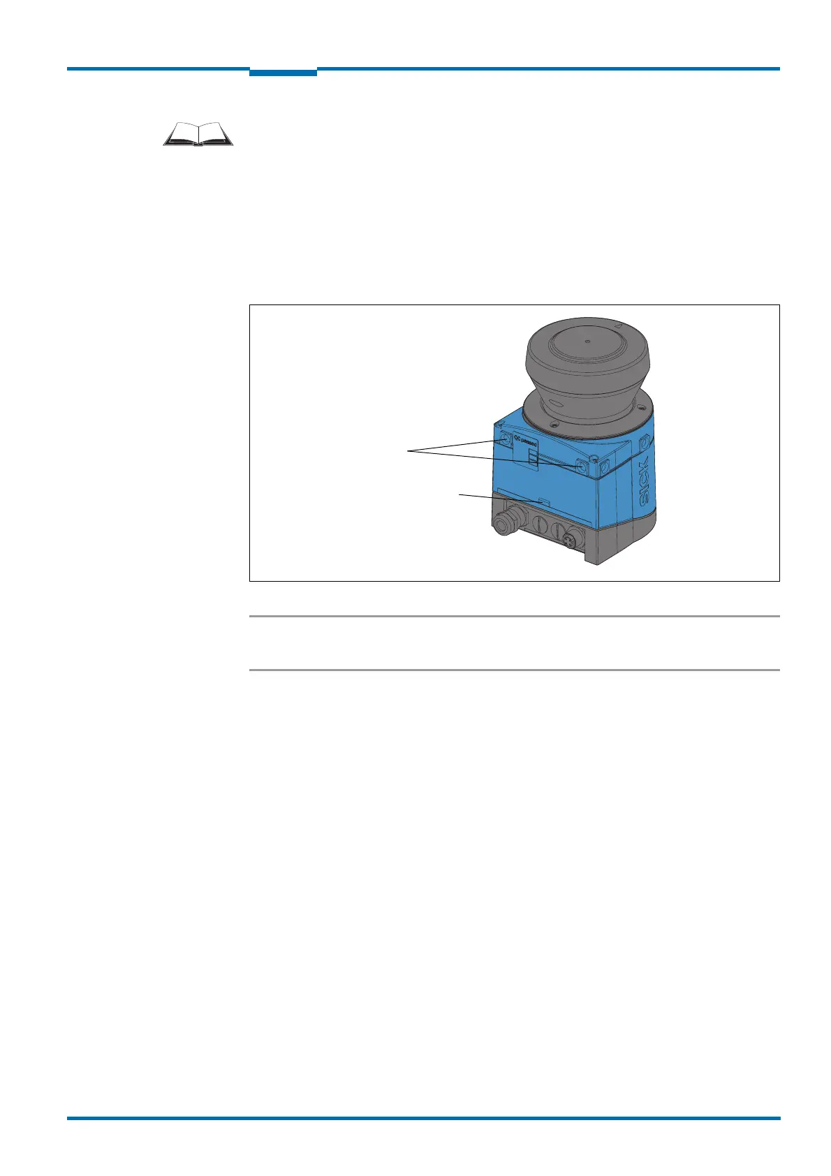
5.3.1 Direct mounting
The LMS1xx has two M5 × 8 threaded holes on the rear. Using them you can mount the
LMS1xx directly on the intended mounting surface. To avoid a possible tendency to vibrate,
the reference surface on the rear can be used as the third mounting point (1).
Fig. 30: Direct mounting
Important During mounting, please observe the dimensional drawings (see section 10.3.1
“Dimensional drawing LMS10x/LMS12x/LMS173/LMC12x” on page 99).