Operating Instructions
LMS1xx Laser Measurement Sensors
Electrical installation
8012471/ZN27/2017-06-09 © SICK AG · Germany · All rights reserved · Subject to change without notice 79
Chapter 6
Connection to an object protection system
LMS12x/LMS13x/LMS14x Security and LMC12x/LMC13x VdS
You will find information on connecting these devices to an object protection system in the
document ”Technical Information (installer instructions VdS)”, part no.: 8013749, issue in
English.
Please see section 1.5 “Further information” on page 9.
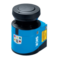
Wiring CAN-interface
To wire the CAN interface a screened “twisted-pair” cable is required. The terminator of
120
must be connected.
Pay attention to max. cable length as per section 6.3.3 “Boundary conditions for the
data interfaces” on page 72.
Fig. 55: Wiring CAN- interface
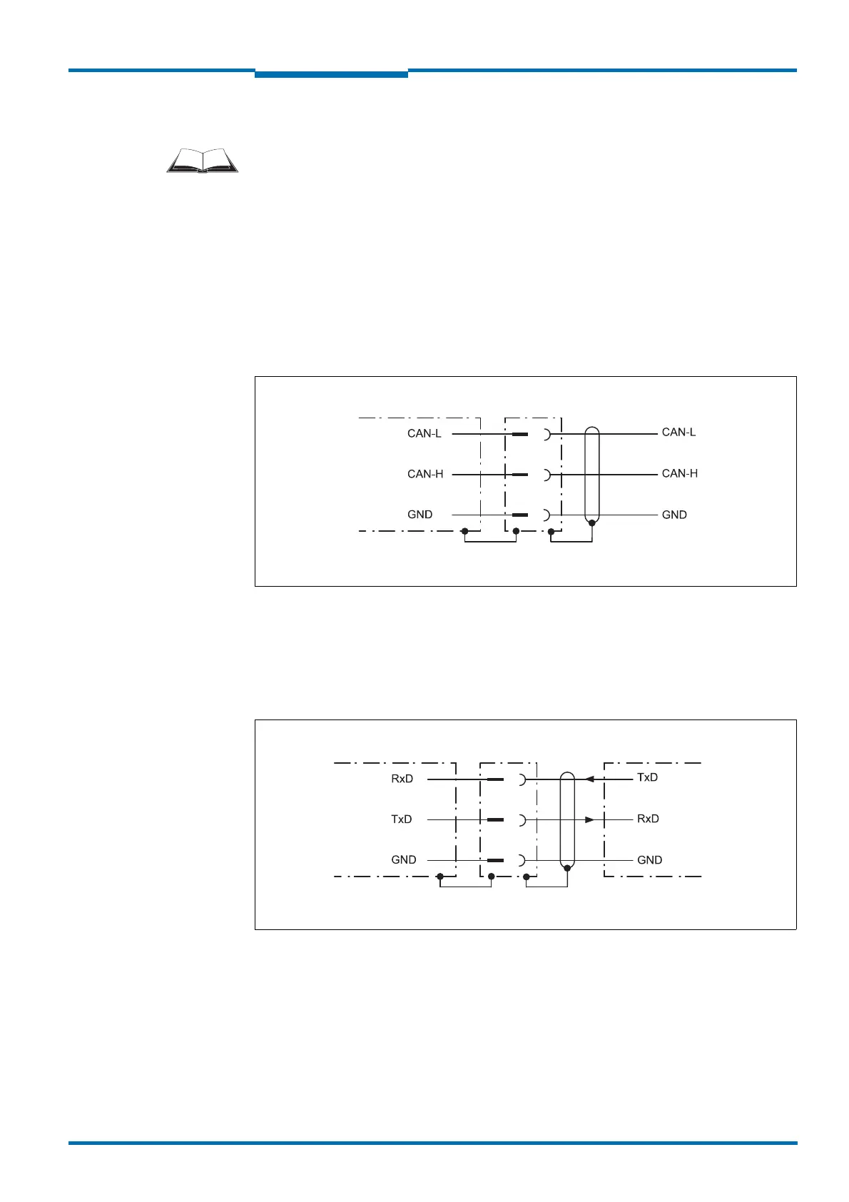
Wiring RS-232 interface
A shielded cable is required for the wiring of the RS-232 interface.
Pay attention to max. cable length as per section 6.3.3 “Boundary conditions for the
data interfaces” on page 72.
Fig. 56: Wiring RS-232 interface