Pin assignment of the voltage supply
Pin Marking Function Wire color
1)
1 +24 V DC 24 V DC supply voltage Brown
2 NC Not connected White
3 0 V DC 0 V DC supply voltage Blue
4 FE Functional earth/shield Black
1)
Applies to the connecting cables recommended as accessories.
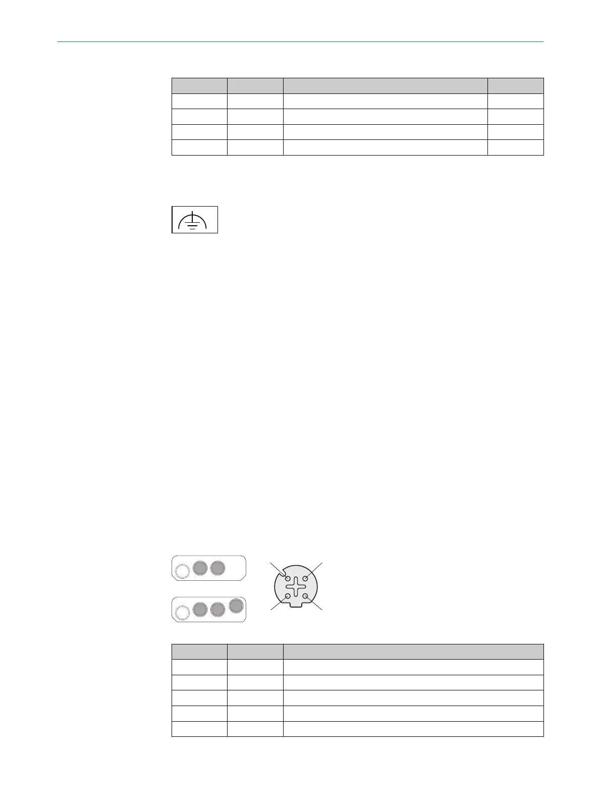
7.2 Alternative FE connection
Figure 1: Alternative FE connection
Screw connection of the alternative FE connection
•
Screw: M5 × 12
•
Tightening torque: 3.5 Nm to 5.0 Nm
Suitable cable lugs
•
Forked cable lug or ring cable lug
•
Width ≤ 10 mm
•
Hole diameter for screw: typically 5.2 mm
The functional earth must be connected via one, and only one of the available FE con‐
nec
tions:
•
Pin on the M12 plug connector
•
Thread on the M12 plug connector
•
Alternative FE connection
The functional earth must be connected in a low-inductance manner and with an ade‐
quate cross-section while keeping the cable length as short as possible. Functional
earth and protection earth must be isolated.
Older system plugs (older than roughly September 2019) might not have an alternative
FE c
onnection.
7.3 Ethernet (XF1, XF2, XF3)
Female connector, M12, 4-pin, D-coded.
Ethernet pin assignment
Pin Designation Function
1 TX+ Send data +
2 RX+ Receive data +
3 TX– Send data -
4 RX– Receive data -
Thread SH Shielding
For the function of the connections, see “C
onnection overview”.
MOUNTING INSTRUCTIONS
14
M O U N T I N G I N S T R U C T I O N S | microScan3 – EFI-pro, microScan3 – EtherCAT®, microScan3 – PROFINET (M12),
micr
oScan3 – EtherNet/IP™
8020210/16V7/2020-03-16 | SICK
Subject to change without notice