The safety laser scanner has 4 M5 threaded holes on the back. If you are able to drill
t
hrough the mounting surface from the rear, you can mount the safety laser scanner
directly using these threaded holes.
b Use either the rear 1 or the side 2 M5 threaded holes for direct mounting.
b
Use all four rear or all four side M5 threaded holes for direct mounting, so that the
values given in the data sheet for vibration and shock resistance are achieved.
b
Maximum depth of thread engagement: 7.5 mm.
b
Tightening torque: 4.5 Nm to 5.0 Nm.
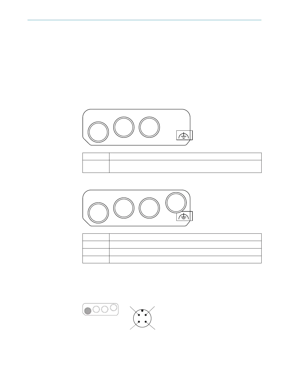
6 Connection overview
MICSX-BANNZZZZ1 (part number: 2086102)
XD1 Voltage supply
XF1, XF2 Ethernet for safety-related data communication, data output, configuration and
dia
gnostics
MICSX-BANNEZZZ1 (part number: 2081021)
XD1 Voltage supply
XF1 Ethernet for EtherCAT IN
XF2 Ethernet for EtherCAT OUT
XF3 Ethernet (not safety-related)
7 Pin assignment
7.1 Voltage supply (XD1)
Male connector, M12, 4-pin, A-coded.
MOUNTING INSTRUCTIONS
8020210/16V7/2020-03-16 | SICK M O U N T I N G I N S T R U C T I O N S | microScan3 – EFI-pro, microScan3 – EtherCAT®, microScan3 – PROFINET (M12),
micr
oScan3 – EtherNet/IP™
13
Subject to change without notice