To avoid a possible tendency to vibrate, the reference surface located on the rear can
be used a
s a third support point if necessary 1.
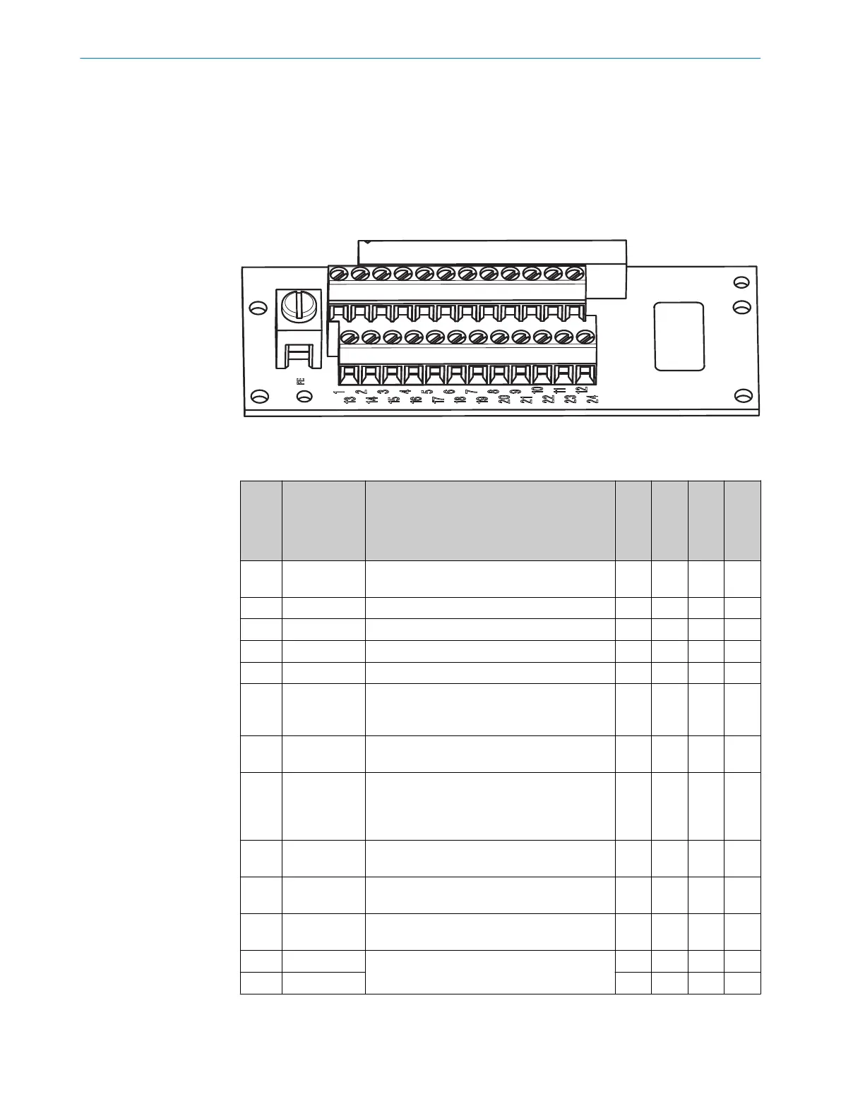
5 Pin assignment
All inputs and outputs of the device are located on the screw connection in the system
plu
g. You can either make the connections directly to the terminal strip on the system
plug or use a pre-assembled system plug from SICK.
Figure 1: Screw terminal block of the system plug
P
in assignment on the system plug
Pin Signal Function
Standard
Advanced
Professional
Expert
FE Functional
earth
C C C C
1 24 V DC Supply voltage S300
C C C C
2 0 V DC Supply voltage S300
C C C C
3 OSSD1 Output signal switching device
C C C C
4 OSSD2 Output signal switching device
C C C C
5 UNI-I/
O1 / R
ESET/
C1
Universal I/O or input, reset, or (for the S300
Professional and Expert) static control input
C
C C C C
6 UNI-I/
O2 / EDM
Universal I/O or input, external device moni‐
toring
C C C C
7 A1 or
IN
C1_0
Static control input A or dynamic control
input (incremental encoder) 1
or connection for a jumper for addressing as
guest
1)
C C C C
8 A2 or
IN
C1_90
Static control input A or dynamic control
input (input for incremental encoder) 1
C C C
9 B1 or
IN
C2_0
Static control input B or dynamic control
in
put (input for incremental encoder) 2
C
2)
C C
10 B2 or
IN
C2_90
Static control input B or dynamic control
input (input for incremental encoder) 2
C
2)
C C
11 RxD–
RS-422 interface to measurement data out‐
put
C C C C
12 RxD+
C C C C
MOUNTING INSTRUCTIONS
10
M O U N T I N G I N S T R U C T I O N S | S300 8025883/2020-08-31 | SICK
Subject to change without notice
 Loading...


