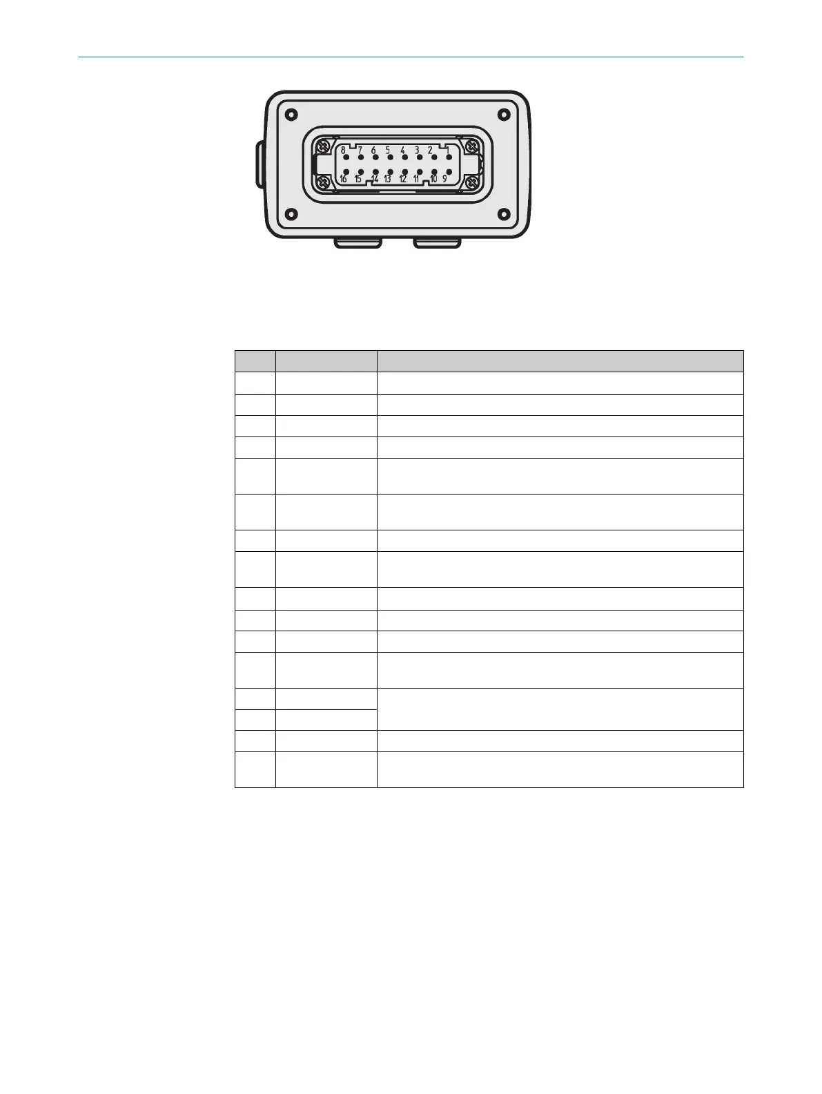
Figure 1: Connector
1
Cable entry
Pin assignment of the connector
Pin Signal Function
1 EFI
A
Enhanced function interface = safe SICK device communication
2 RxD RS-232 interface to the PC
3 B1 Static control input B
4 0 V DC for heater Supply voltage for the heater
5 ERR Application diagnostic output for error/contamination or connection
f
or a jumper for addressing as guest
1)
6 A1 Static control input A or connection for a jumper for addressing as
guest
1)
7 A2 Static control input A
8 0 V DC for scan‐
ner
Supply voltage for the safety laser scanner
9 EFI
B
Enhanced function interface = safe SICK device communication
10 TxD RS-232 interface to the PC
11 B2 Static control input B
12 +24 V DC for
he
ater
Supply voltage for the heater
13 OSSD1
Output signal switching device
14 OSSD2
15 WF Output for Object in the warning field
16 +24 V DC for
sc
anner
Supply voltage for the safety laser scanner
1)
In order to operate 2 safety laser scanners in an EFI system, you must define a device as a guest using a
br
idge between pin 5 and pin 6. This is also required if several safety laser scanners are connected to
one EFI string on a Flexi Soft safety controller.
MOUNTING INSTRUCTIONS
8
M O U N T I N G I N S T R U C T I O N S | S3000 Cold Store 8025885/2020-08-31 | SICK
Subject to change without notice