Chapter 3 Addendum Operating Instructions
S3000 PROFINET IO/IOOF
8 © SICK AG • Industrial Safety Systems • Germany • All rights reserved 8013291/YY95/2016-02-05
Subject to change without notice
Product description
Services supported
PROFINET IO with Conformance Class B
LLDP according to IEEE 802.1 AB
SNMP
MIB-II
cyclic IO communication
acyclic read/write services for communication via TCI interface
diagnostics alarms
TCP/IP communication via port 9000
support for MRP client
3.3 Input signals
3.3.1 Reset signals
If the safety laser scanner is operated using the “With restart interlock” function, then
after a protective field interruption and the subsequent clearing of the protective field, the
S3000 PROFINET IO/IO8OF requests a reset signal from the control system (Reset Re-
quired). The safety laser scanner reacts to an edge change on the reset signal from low to
high (not to the level).
The reset signal must be fail-safe (single failure proof)!
3.3.2 Control signals for switching monitoring cases
You can switch between protective fields by switching monitoring cases.
The related control inputs A, B, C, D on theS3000 PROFINET IO/IO8OF Professional or A, B
on the S3000 PROFINET IO/IO8OF Advanced expect complementary signals.
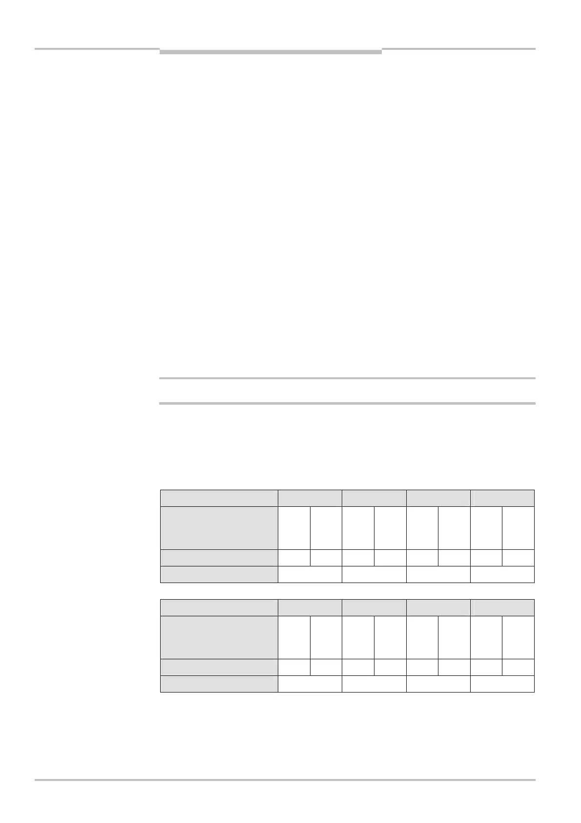
Control input A B C D
Bits of the output byte 0 in
the process image (see
Tab. 10 on page 32)
0.0 0.1 0.2 0.3 0.4 0.5 0.6 0.7
Value of the bit 1 0 1 0 1 0 1 0
Logical state 0 0 0 0
Control input A B C D
Bits in output byte 0 in the
process image (see
Tab. 10 on page 32)
0.0 0.1 0.2 0.3 0.4 0.5 0.6 0.7
Value of the bit 0 1 0 1 0 1 0 1
Logical state 1 1 1 1
Examples:
01011010 = valid value: A = 1, B = 1, C = 0, D = 0
11011010 = invalid value, input A is not set complementarily
WARNING
Note
control inputs in the process
image
control inputs in the process
image