6 Electrical installation
6.1 Safety
WARNING
Personal injury due to improper supply voltage!
■
Only operate the device using safety extra-low voltage and safe electrical insula‐
tion as per protection class III.
NOTICE
Equipment damage or unpredictable operation due to working with live parts.
Working with live parts may result in unpredictable operation.
■
Only carry out wiring work when the power is off.
■
Only connect and disconnect electrical connections when the power is off.
6.2 Electrical connection of the sensor
NOTICE
All electrical circuits must be connected to the device with safety extra-low voltage
(SELV or PELV).
Protect the device with an external 0.8A slow-blow fuse at the beginning of the supply
cable.
1. Ensure that the voltage supply is not connected.
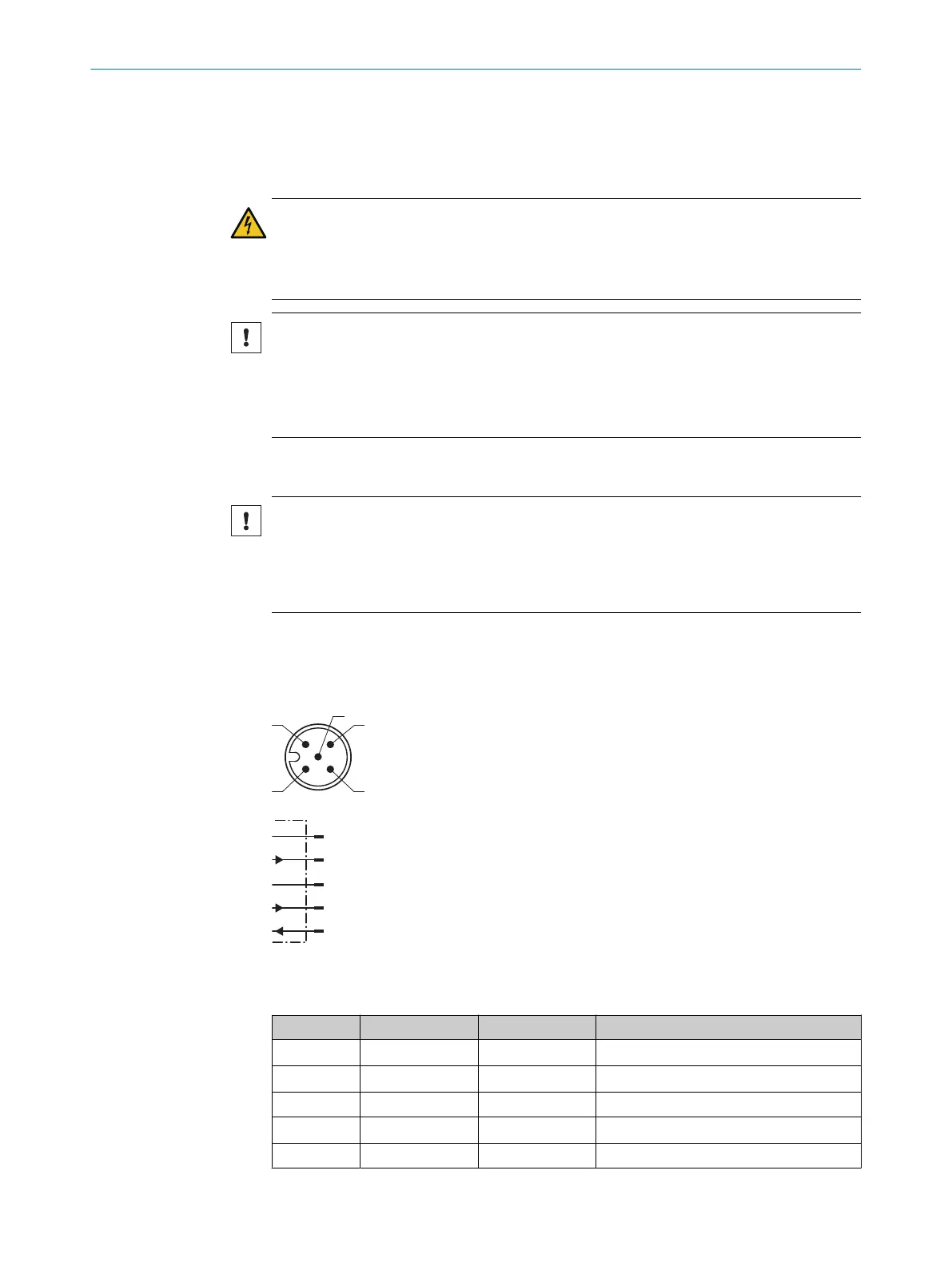
2. Connect the device as shown in the connection diagram and electrical block
diagrams.
L+
1
brn
M
3
blu
IO-Link/Q1
4
blk
Q2
2
wht
In/MF
5
gra
Figure 5: Connection diagram TiM1xx, 5-pin male connector
Table 2: Legend for connection diagram
Contact Identification Wire color Description
1 L+ Brown Supply voltage V
S
2 Q
2
White Digital output 2
3 M Blue Supply voltage GND
4 IO-Link/Q
1
Black IO-Link/digital output 1
5 In/MF Gray Input/multifunctional input
6 ELECTRICAL INSTALLATION
18
O P E R A T I N G I N S T R U C T I O N S | TiM1xx 8020631/1DWW/2022-08 | SICK
Subject to change without notice