BZ int49
Detailed addresses and further locations at www.sick.com
Australia
Phone +61 (3) 9457 0600
1800 33 48 02 – tollfree
Austria
Phone +43 (0) 2236 62288-0
Belgium/Luxembourg
Phone +32 (0) 2 466 55 66
Brazil
Phone +55 11 3215-4900
Canada
Phone +1 905.771.1444
Czech Republic
Phone +420 234 719 500
Chile
Phone +56 (2) 2274 7430
China
Phone +86 20 2882 3600
Denmark
Phone +45 45 82 64 00
Finland
Phone +358-9-25 15 800
France
Phone +33 1 64 62 35 00
Germany
Phone +49 (0) 2 11 53 010
Greece
Phone +30 210 6825100
Hong Kong
Phone +852 2153 6300
Hungary
Phone +36 1 371 2680
India
Phone +91-22-6119 8900
Israel
Phone +972 97110 11
Italy
Phone +39 02 27 43 41
Japan
Phone +81 3 5309 2112
Malaysia
Phone +603-8080 7425
Mexico
Phone +52 (472) 748 9451
Netherlands
Phone +31 (0) 30 229 25 44
New Zealand
Phone +64 9 415 0459
0800 222 278 – tollfree
Norway
Phone +47 67 81 50 00
Poland
Phone +48 22 539 41 00
Romania
Phone +40 356-17 11 20
Russia
Phone +7 495 283 09 90
Singapore
Phone +65 6744 3732
Slovakia
Phone +421 482 901 201
Slovenia
Phone +386 591 78849
South Africa
Phone +27 10 060 0550
South Korea
Phone +82 2 786 6321/4
Spain
Phone +34 93 480 31 00
Sweden
Phone +46 10 110 10 00
Switzerland
Phone +41 41 619 29 39
Taiwan
Phone +886-2-2375-6288
Thailand
Phone +66 2 645 0009
Turkey
Phone +90 (216) 528 50 00
United Arab Emirates
Phone +971 (0) 4 88 65 878
United Kingdom
Phone +44 (0)17278 31121
USA
Phone +1 800.325.7425
Vietnam
Phone +65 6744 3732
Subject to change without notice
Irrtümer und Änderungen vorbehalten
WT100L / WL100L
WS / WE100L
EN/IEC 60825-1:2014
Laser
1
Maximum pulse power: 3 mW
Puls length: 1 µs
Wavelength: 655 nm
Complies with 21 CFR 1040.10
and 1040.11 except for deviations
pursuant to Laser Notice No. 56,
dated May 8, 2019
LASER CLASS 1
EN/IEC 60825-1:2014
Laser
1
Maximum pulse power: 0.6 mW
Puls length: 1.2 µs
Wavelength: 655 nm
Complies with 21 CFR 1040.10
and 1040.11 except for deviations
pursuant to Laser Notice No. 56,
dated May 8, 2019
LASER CLASS 1
Safety specications
> Read the operating instructions before starting operation.
> Connection, assembly, and settings only by competent techni-
cians.
> Protect the device against moisture and soiling when operating.
> No safety component in accordance with EU machine guidelines.
> CAUTION: Use of controls or adjust ments or performance of proce-
dures other than those specied herein may result in hazardous
radiation exposure.
Proper use
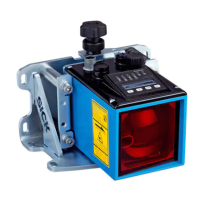
The W100L photoelectric proximity switch is an optoelectronic sensor
and is used for detection of optical, non-contact detection of objects
and animals.
WT100L
• Check the application conditions such as size and reectance ca-
pacity of the object as well as background inuences and compare
with the sensitivity characteristic curve of the WT type.
• Direct scanner onto the object to be probed. In the horizontal / ver-
tical direction determine the on / o switching point of the signal
strenght indicator and select central position.
• Remove object and set sensitivity to “max.”.
• Signal strength indicator does not light up: setting is competed.
• Signal strenght indicator lights up: reduce sensitivity until signal
strength indicator goes out. Position object.
• Signal strength indicator must light up otherwise turn sensitivity
control in the direction of “max.” until the signal strength indicator
lights up.
• Remove object. Signal strength indicator goes out. Setting
completed.
• Signal strength indicator lights up: background inuence to strong.
Check setting and application.
WL100L
• Align photoelectric switch and reector to one another (reector
P250F included in scope of supply). The red light spot is visible on
the reector.
• In the horizontal / vertical direction determine on / o switching
points of the signal strength indicator and select central position.
The signal strength indicator must light up.
WS / WE100L
• Align sender and receiver to one another.
• In the horizontal / vertical direction determine the on / o switching
points of the signal strength indicator and select central position.
WT100L / WL100L
WS / WE100L
EN/IEC 60825-1:2014
Laser
1
Maximale Pulsleistung: 3 mW
Impulsdauer: 1 µs
Wellenlänge: 655 nm
Entspricht 21 CFR 1040.10
und 1040.11 mit Ausnahme von
Abweichungen nach
Laser-Hinweis 56, 08. Mai 2019
LASERKLASSE 1
EN/IEC 60825-1:2014
Laser
1
Maximale Pulsleistung: 0,6 mW
Impulsdauer: 1,2 µs
Wellenlänge: 655 nm
Entspricht 21 CFR 1040.10
und 1040.11 mit Ausnahme von
Abweichungen nach
Laser-Hinweis 56, 08. Mai 2019
LASERKLASSE 1
Sicherheitshinweise
> Vor der Inbetriebnahme die Betriebs anleitung lesen.
> Anschluss, Montage und Einstellung nur durch Fachpersonal.
> Gerät bei Inbetriebnahme vor Feuchte und Verunreinigung
schützen.
> Kein Sicherheitsbauteil gemäß EU- Maschinenrichtlinie.
Bestimmungsgemäße Verwendung
Der Reexions-Lichttaster W100L ist ein optoelektronischer Sensor
und wird zum optischen, berührungslosen Erfassen von Sachen und
Tieren eingesetzt.
WT100L
• Einsatzbedingungen wie Größe und Remis-
sions vermögen des Objekts sowie Hintergrund einüsse überprüfen
und mit der Empndlichkeitskennlinie des WT-Typs vergleichen.
• Taster auf das Tastgut ausrichten. In horizontaler- / vertikaler
Richtung Ein- / Ausschaltpunkt der Empfangsanzeige ermitteln
und Mittelstellung wählen.
• Objekt entfernen und Empndlichkeit auf „max.“ stellen.
• Empfangsanzeige leuchtet nicht: Einstellung beendet.
• Empfangsanzeige leuchtet: Empndlichkeit reduzieren bis die
Empfangsanzeige erlischt. Objekt positionieren.
• Wenn Empfangsanzeige nicht leuchtet, Drehknopf Richtung
„max.“ drehen bis Empfangs anzeige leuchtet.
• Objekt entfernen. Empfangsanzeige erlischt. Einstellung beendet.
• Empfangsanzeige leuchtet: Hintergrundeinuss zu stark. Applika-
tion und Einstellung überprüfen.
WL100L
• Lichtschranke und Reektor aufeinander ausrichten (Reektor
P250F im Lieferumfang enthalten). Der rote Lichteck ist auf dem
Reektor sichtbar.
• In horizontaler / vertikaler Richtung Ein- / Ausschaltpunkt der
Empfangsanzeige ermitteln und Mittelstellung wählen. Empfangs-
anzeige muss leuchten.
WS / WE100L
• Sender und Empfänger auf einander ausrichten.
• In horizontaler / vertikaler Richtung Ein- / Ausschaltpunkt der
Empfangsanzeige ermitteln und Mittelstellung wählen.
W100 Laser
WT100L-Xxxxx
WL100L-Xxxxx
WS100L-Xxxxx
WE100L-Xxxxx
WS100L-D2131
L+
M
BN
BU
BK
WT100L-F2241
WT100L-E2241
WL100L-F2231
WL100L-E2231
WE100L-F2231
WE100L-E2231
L+
M
Q
BN
BU
WH
BK
WS100L-D2231
L+
M
BN
BU
WH
BK
WT100L-F1141
WT100L-E1141
WL100L-F1131
WL100L-E1131
WE100L-F1131
WE100L-E1131
M
Q
BN
BU
BK
WS100L-D1131
BN
BU
M
WT100L-F2141
WT100L-E2141
WL100L-F2131
WL100L-E2131
WE100L-F2131
WE100L-E2131
L+
M
Q
BN
BU
BK
1
Befestigungsgewinde M3 / Mounting hole M3
2
Mitte Optikachse, Empfänger / Centre of optical axis, receiver
3
Mitte Optikachse, Sender / Centre of optical axis, sender
4
Anschluss / Connection
5
LED-Anzeige orange: Schaltausgang
Leuchtet, wenn der Lichtempfang über der Schaltschwelle liegt /
LED indicator orange: switching output
Lights up if the light receiver lies above the switching threshold
6
LED-Anzeige grün: Funktionsreserve
Leuchtet bei Lichtempfang mit Funktionsreserve >1,1 und <0,9M /LED indicator green: operating
reserve
Lights up with light reception with operating reserve >1.1 and <0.9
7
Schaltabstandeinsteller 270° /
Operating distance adjustment 270°
8
Hell- / Dunkeldrehschalter:
L: hellschaltend, D: dunkelschaltend /
Light / dark rotary switch:
L: light-switching, D: dark-switching
--------------------------------------------------------------------------------------- 8 0 1 1 7 9 7 . 1 G K Q / 0 5 6 4 0 1 3 0 1 2 4 ------------------------------------------------------------------------------------------
2006/42/EC
NO
SAFETY
SICK AG, Erwin-Sick-Strasse 1, DE-79183 Waldkirch
LD
20 (0.79)
3
(0.12)
25.4 (1.00)
(0.11)
31 (1.22)
10.3
(0.41)
(0.43)
19.8
(0.78)
13.4
(0.53)
1
1
2
3
4
(0.43)
19.8
(0.78)
2
3


 To Next Page
 Need help?
 General