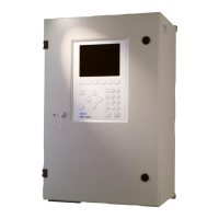
Do you have a question about the SICK MARSIC200 and is the answer not in the manual?
Details the scope of the document, including installation and operation procedures.
Identifies the intended audience and their required technical understanding and training.
Lists related operating instructions and system documentation for additional reference.
Explains warning symbols, signal words, and information symbols used throughout the manual.
Defines terms for gases used, including zero gas, span gas, and instrument air.
Provides general information on power supply and gas supply considerations for installation.
Details requirements and precautions for electrical power supply connections.
Provides guidance and warnings regarding instrument air and zero gas supply quality.
Illustrates and explains the procedure for using tube screw fittings correctly.
Directs users to delivery documents for a complete list of included items.
Lists items and resources that the operator must provide for installation.
Provides a visual overview of system components and their interconnections.
Illustrates system configurations for one to four measuring points with component connections.
Provides a checklist to ensure all mechanical and electrical installation steps are completed.
Details the steps for properly installing the system enclosures.
Guides the process of laying and connecting various gas lines.
Explains how to lay and connect electric lines between key system components.
Details the procedure for laying and connecting electric lines to the analyzer.
Guides the installation of the sampling probe, including orientation and timing.
Details the process of laying and connecting the heated sample gas line.
Covers the steps for installing the sample conditioning unit and its components.
Provides instructions for fitting the sample conditioning enclosure and internal parts.
Shows the connection points for gas lines on the sample conditioning unit.
Details the electrical connections required for the sample conditioning unit.
Provides an overview and steps for installing the distribution unit.
Provides instructions for fitting the distribution unit enclosure and internal parts.
Shows the connection points for gas lines on the distribution unit.
Details the electrical connections required for the distribution unit.
Explains the function and installation of the measuring point switchover.
Guides the installation of the analyzer unit, including exterior and interior views.
Provides instructions for fitting the analyzer enclosure and ensuring proper clearances.
Shows the connection points for gas lines on the analyzer unit.
Details the electrical connections required for the analyzer unit.
Details the prerequisite checks and operational steps for system initialization and warm-up.
Describes the process of installing, connecting, and using SOPAS ET for device configuration.
Lists the user levels and their corresponding passwords for system access.
Explains how to program test gas settings for adjustments and validation measurements.
Details the steps for manually initiating and performing an adjustment or validation procedure.
Describes how to set up and execute automatic adjustment and validation procedures.
Explains the functionality and programming of automatic adjustment and validation procedures.
Outlines the different options for starting automatic adjustment and validation procedures.
Details the process of programming automatic adjustment and validation routines.
Notes that SOPAS ET software is required for performing tests and settings.
Explains how to synchronize the system's date and time with a PC.
Guides testing and configuration of digital and analog inputs and outputs.
Details how to test and verify the functionality of digital inputs.
Details how to test and verify the functionality of digital outputs.
Details how to test and verify the functionality of analog outputs.
Describes how to adapt analog signals when deviations are detected during hardware checks.
Provides detailed steps for setting analog interfaces, including inputs and outputs.
Explains how to configure and manage measured values within the system.
Covers the automatic control and switching of up to eight measuring points.
Explains the functionality of the automatic measuring point switching.
Outlines the requirements and configurations for automatic measuring point operation.
Details the process of configuring the automatic operation of measuring points.
Explains how to create, store, and restore system parameter backups.
Provides overall dimensional drawings and necessary clearances for system components.
Provides detailed dimensional drawings for the sample conditioning unit.
Provides detailed dimensional drawings for the distribution unit.
Provides detailed dimensional drawings for the analyzer unit.
Provides detailed dimensional drawings for the sampling probe.
Provides technical drawing and specifications for the heated sample gas line.
Illustrates the flow paths of gases through the system for single-point measurement.
Lists configurable measuring parameters, including variants, methods, and ranges.
Specifies the operating temperature, humidity, and pressure requirements for the system.
Details the characteristics of sample gas at the measuring point, including temperature and pressure.
Describes the design of the wall enclosure and the materials used for system components.
Provides technical data for the heated sample gas line, including temperature and power specifications.
Lists supported interfaces, communication protocols, and status indicators.
Details the power supply requirements, consumption, and system power inputs.
Mentions condensate quantity generated from water vapour-saturated exhaust gas.
Specifies torque values for various screw fittings used during assembly.
Lists the dimensions and connection types for various tubes and couplings.
Reiterates gas quality, inlet pressure, and flow rate for instrument air, zero, and span gases.
| Brand | SICK |
|---|---|
| Model | MARSIC200 |
| Category | Measuring Instruments |
| Language | English |


