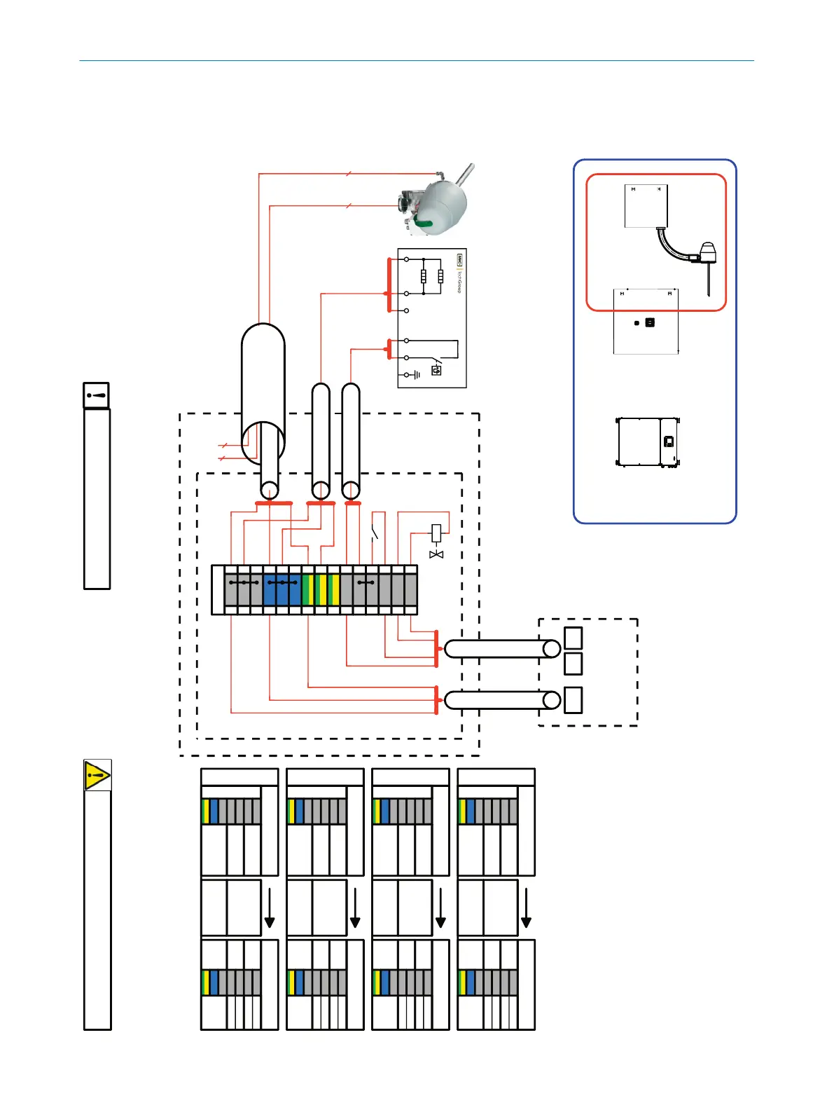
To sampling Probe (Power)
Marine Line (3x1,5) 6056215
Preparation Unit (UM1) Distribution unit (UM5)
10
13
14
15
1
4
7
1
2
14
18
1
2
3
Alarm
Valve KK10
Power
Marine Line
(4x0,75)
6056229
Marine Line
(3x1,5)
6056215
XD21
XD61
XD2
To distributor unit (Power)
Marine Line (3x1,5) 6056215
To distributor unit (Signal)
Marine Line (4x0,75) 6056229
Power
+24V
XD1
DI 1
0V
control
2
2
gy
3
3
gy
bu
4
4
bu bu
5
5
6
6
gnye
7
7
gnye
8
8
gnye
9
9
1
1
gy
10
10
gy
gy
11
11
gy
12
12
gy
13
13
gy
14
14
gy
15
15
PE
L
N
Line 1
Distribution unit
(see next Page for details)
UM1
UM5
BQ1
UC1
sample gas line
UM1
junction box
UM5
XD2XD21 XD61
All cable diameters are proposals! The customer must check this diameters!
Parameters are e.g.: voltage drop, cable cluster, laying procedure etc.
WD3
WD6
WD2
WD1
Preparation Unit (UM2) Distribution unit (UM5)
10
13
14
15
1
4
7
3
4
15
19
1
2
3
Alarm
Valve KK10
Power
Marine Line
(4x0,75)
6056229
Marine Line
(3x1,5)
6056215
XD21
XD61
XD2
Power
+24V
XD1
DI 2
0V
control
Line 2
XD1
Preparation Unit
L PEN
PE
L
N
Preparation Unit (UM3) Distribution unit (UM5)
10
13
14
15
1
4
7
5
6
16
20
1
2
3
Alarm
Valve KK10
Power
Marine Line
(4x0,75)
6056229
Marine Line
(3x1,5)
6056215
XD21
XD61
XD2 Power
+24V
XD1
DI 3
0V
control
Line 3
4 5
5
4
To sampling Probe (signal)
Marine Line (4x0,75) 6056229
Preparation Unit (UM4) Distribution unit (UM5)
10
13
14
15
1
4
7
7
8
17
21
1
2
3
Alarm
Valve KK10
Power
Marine Line
(4x0,75)
6056229
Marine Line
(3x1,5)
6056215
XD21
XD61
XD2 Power
+24V
XD1
DI 4
0V
control
Line 4
Connection of the sample preparation
is always the same
5...15m
54
L
2
N
3
6
200W
200W
PE
1
PE
rdbu
KK10
A
EC1
IN
rd
bu
13
-EC1
x1
x2
-KK10