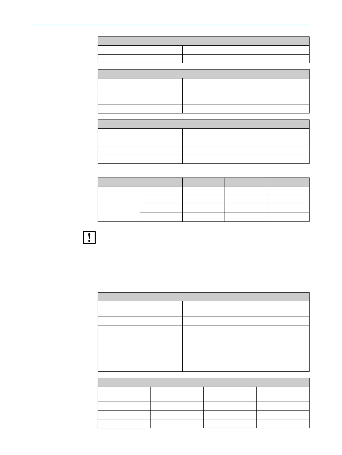
Analog inputs
Input load 50 Ω
Transducer precision 0,5 %
Digital inputs
Design Optical coupler
Number 8
Switching range 18 … 42 V
Highest allowable voltage ±50 V DC
Digital outputs
Number 16
Contact type: 1-pole changeover switch, 3 connections
Contact load: See Table below
Highest allowable voltage ±50 V DC
Table 7: Maximum load per relay switching contact
Application area AC voltage DC voltage Current
Standard: Max. 30 VAC Max. 48 VAC Max. 500 mA
CSA Either Max. 30 VAC Max. 48 VAC Max. 50 mA
or Max. 15 VAC Max. 24 VAC Max. 200 mA
or Max. 12 VAC Max. 18 VAC Max. 500 mA
NOTICE
Only use discharging diodes to connect inductive loads (e.g., relays, solenoid valves) to
the switching outputs.
•
For inductive loads: Check that discharging diodes are fitted.
•
If this is not the case: Install external discharging diodes.
7.9 Energy supply
Power supply
Supply voltage 115/230 VAC, 50/60 Hz
Deviating power supply via upstream transformer
Current 8 A (with 230 V)
Power consumption
•
Sampling probe
•
Sample gas line
•
Sample conditioning
•
Distribution unit
•
Analyzer
Power consumption
•
400 VA
•
60 VA/m
•
150 VA
•
200 VA (1 MPI), 300 VA (2 ... 4 MPI)
•
300 VA
Power input, complete system (max. for each 5 m sample gas line)
Number of measuring
points
Power consumption Current (230 VAC) Current (115 VAC)
1 1400 VA 6 A 12 A
2 2300 VA 10 A 20 A
3 3200 VA 14 A 28 A
7 TECHNICAL DATA
64
T E C H N I C A L I N F O R M A T I O N | MARSIC200 8017324/15A2/V6-0/2019-10 | SICK
Subject to change without notice