2.10.2 Gas connections on distribution unit
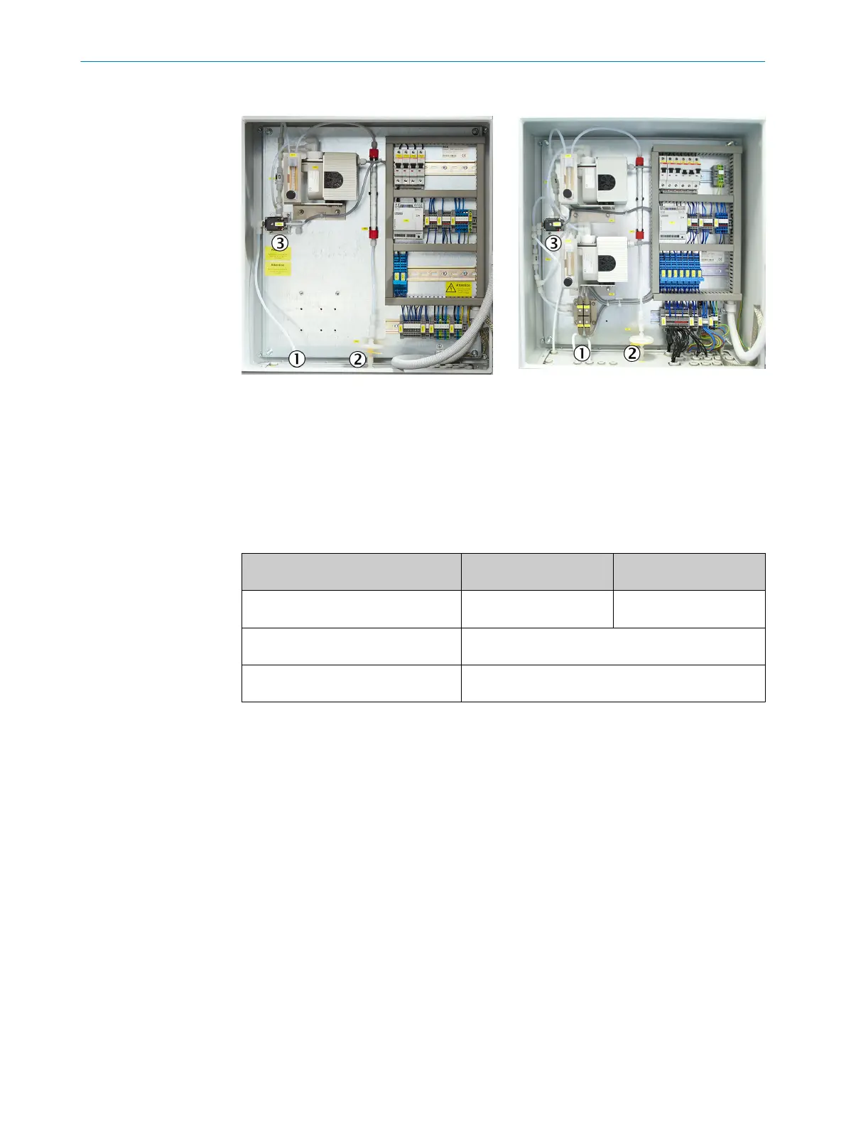
Figure 13: SINGLE version distribution unit for
one measuring point (example)
1
Gas inlet from sample conditioning(s)
2
Gas outlet to analyzer
3
Valve KK1
Figure 14: MULTI version distribution unit for
two to four measuring points (example)
1
Connection of PTFE line from sample
conditioning
2
Connection of PTFE line to analyzer
3
Valve KK1
b
Lay all PTFE tubes into the enclosure from the bottom.
b
Connect the lines.
Line Connection of
SINGLE version
Connection of
MULTI version
PTFE line from sample conditioning
(sample gas inlet)
Valve KK1, inlet “R” Measuring point
switchover “P1-P4”
PTFE line to analyzer (sample gas out‐
let)
Sample gas outlet on the enclosure outside
Test gas inlet (zero gas: nitrogen or
instrument air)
1
Valve KK1, inlet “P”
1
This gas is used as zero gas during automatic zero point adjustment. When the reference point is
adjusted via the distribution unit (not via the sampling probe), the span gas must be connected to this
inlet during the adjustment.
2 INSTALLATION
30
T E C H N I C A L I N F O R M A T I O N | MARSIC200 8017324/15A2/V6-0/2019-10 | SICK
Subject to change without notice