2.11 Installing the analyzer
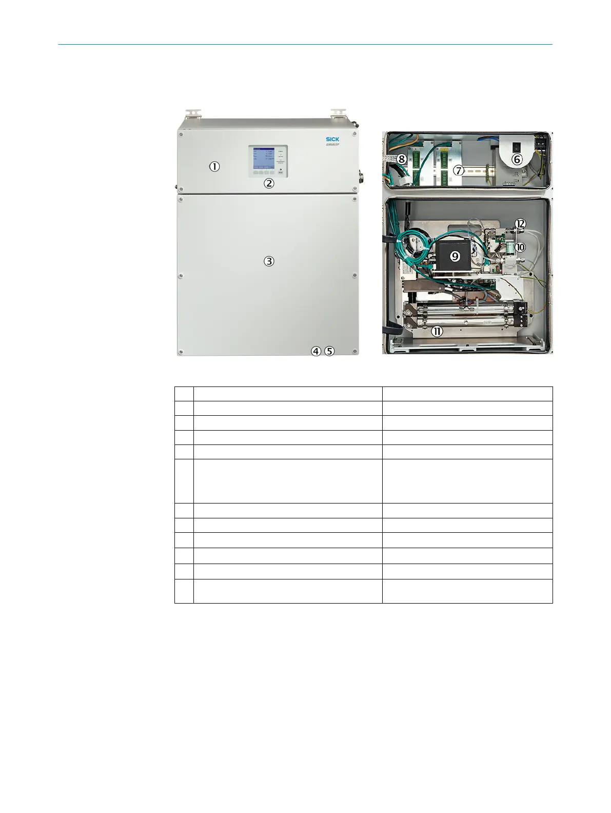
Exterior view
Figure 17: Analyzer (exterior view)
Figure 18: Analyzer (interior view)
1
Analyzer top part with electronics
2
Control unit
3
Analyzer bottom part with measurement technology
4
Sample gas inlet Screw fitting: DN4/6 stainless steel
5
Sample gas outlet Screw fitting: DN4/6 stainless steel
6
On/Off switch The On/Off switch switches the analyzer on/off.
•
The digital outputs switch to “Zero”
•
The analog outputs switch to “Zero”
7
Data interfaces Analog and digital inputs and outputs
8
Fuse Check the fuse
9
Measuring module CO
2
(FINOR)
ß
Measuring module O
2
(OXOR E) optional
à
Measuring module SO
2
/NO
x
(DEFOR)
á
Measuring module flow/humidity/pressure (gas
module)
INSTALLATION 2
8017324/15A2/V6-0/2019-10 | SICK T E C H N I C A L I N F O R M A T I O N | MARSIC200
33
Subject to change without notice