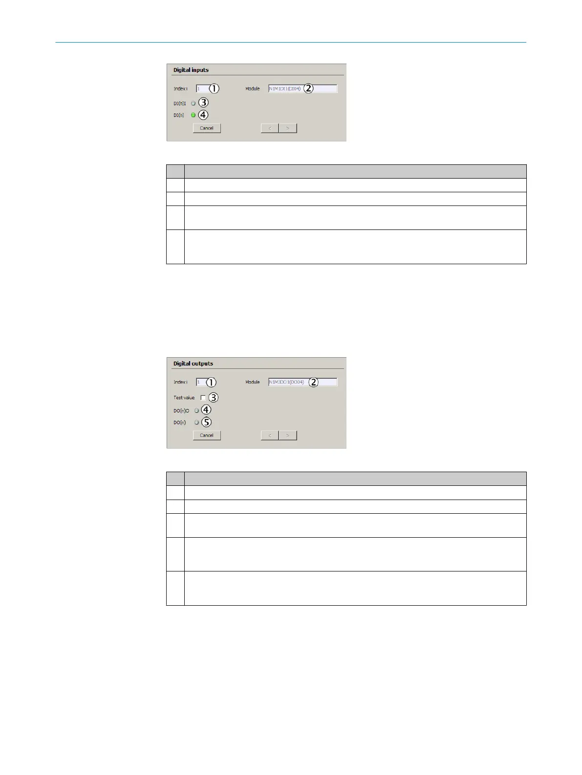
Figure 27: Test digital inputs
Significance
1
Number of selected input.
2
Topographic addressing.
3
[State]
Computed value of [Source] (“Inverted” is taken into consideration).
4
[Source]
LED is off: Physical contact open.
LED is on: Physical contact closed.
6.3.2 Digital outputs
Menu: Parameter/I/O/Digital output
Select the digital output to be tested and click “Test”.
The digital output can be activated or deactivated for the function check using the
checkmark (see “Test value” in the Figure below).
Figure 28: Test of digital outputs
Significance
1
Number of selected output.
2
Topographic addressing.
3
No checkmark: Physical contact should be open.
Checkmark: Physical contact should be closed.
4
[State]
LED is off: Relay energized.
LED is on: Relay de-energized.
5
[Source]
LED is off: Program specification: Physical contact should be open.
LED is on: Program specification: Physical contact should be closed.
Set the checkmark next to the Test value checkbox.
The status of the LEDs changes.
Use an ohmmeter to check the status of the relay outputs on X4 (DO 1-4) and X5 (DO
5-8).
If relay outputs do not function, the I/O modules must be exchanged because they can‐
not be repaired onsite.
6
TESTS AND SETTINGS
48
T E C H N I C A L I N F O R M A T I O N | MARSIC200 8017324/15A2/V6-0/2019-10 | SICK
Subject to change without notice