2.11.1 Fitting the analyzer
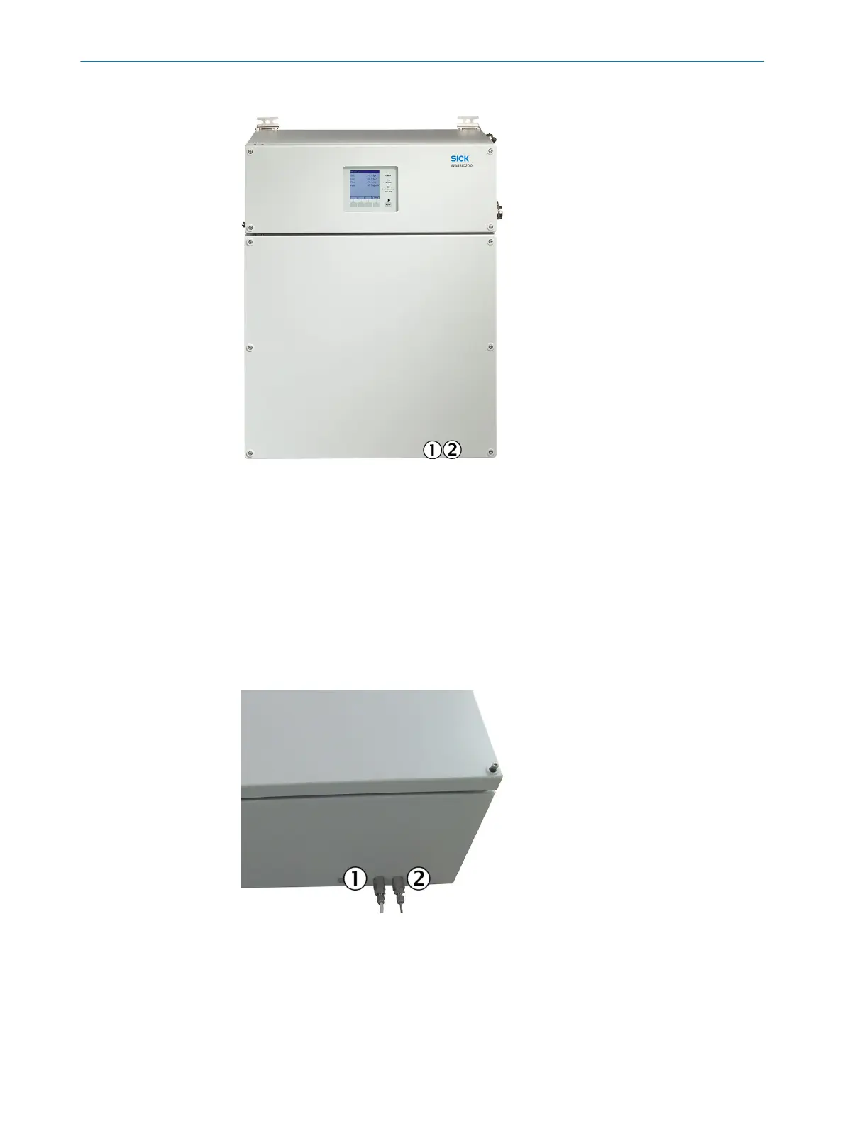
Figure 19: Clearance for PTFE lines
1
PTFE line (sample gas inlet)
2
PTFE line (sample gas outlet)
b
Fasten the analyzer on a suitable panel using the mounting bracket provided.
°
Drilling plan: see "Dimensional drawings", page 55.
°
Fit the enclosure horizontal.
°
Observe the clearance for the PTFE line: see "Dimensional drawings",
page 55.
°
Observe the relevant ambient conditions: see "Technical data", page 55.
2.11.2 Gas connections on analyzer
1
Sample gas inlet (seen from the front,
bottom left)
2
Sample gas outlet (seen from the front,
bottom right)
b
Lay all PTFE tubes into the enclosure from the bottom.
b
Connect the lines.
2 INSTALLATION
34
T E C H N I C A L I N F O R M A T I O N | MARSIC200 8017324/15A2/V6-0/2019-10 | SICK
Subject to change without notice