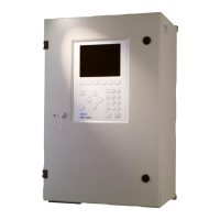
Do you have a question about the SICK MARSIC300 and is the answer not in the manual?
Explains the document's purpose and scope, covering installation and initial start-up.
Identifies the intended audience and their necessary technical qualifications for operation.
Lists related documents and additional resources for users seeking more information.
Explains symbols, signal words, and conventions used throughout the manual for clarity.
Defines terms related to utility gases like zero gas, span gas, and instrument air.
Covers power supply, gas supply quality, and tube fitting procedures.
Refers to delivery documents and lists items provided by the operator.
Diagram of components and a checklist for mechanical/electrical installation.
Instructions for laying and connecting gas lines and tube bundle cables.
Details on mounting the analyzer cabinet, including dimensions and clearances.
Step-by-step guide for connecting sample gas lines and tube bundle cables.
Instructions for connecting signal lines and air/gas to the analyzer.
Procedures for making electrical connections, including power supply.
Steps for installing the gas sampling system, including flange fitting.
Guide to configuring the optional Modbus-Profinet converter.
Essential checks and preparations before powering on the system.
Steps for powering on the system and observing the boot sequence.
Post-startup checks, internal adjustment, and network configuration.
Introduction to SOPAS ET for device configuration and logbook access.
Procedures for saving, backing up, and restoring device parameters.
Information on user access levels and password management.
Overview of the menu structure available within the SOPAS ET software.
Explains how to configure up to eight display screens for measurements.
Describes display options like measured value boxes, bar graphs, and line writer.
Details on storing data and scaling measuring screens.
Defines global settings and specific parameters for measuring components.
Explains how to configure and select different measuring screen layouts.
Covers setting start times, manual, and automatic adjustments.
Configures programs for measuring at multiple sampling points.
Details on configuring digital inputs/outputs, OPC, and Modbus.
Settings for Modbus values, input values, and flags.
Configuration for temperature, pressure, flow, O2 sensor, logbook, display, system, and emitter.
Monitors drift, reference energy, intensity, sensor values, and signals.
Displays status of digital, measuring, internal, boolean, real, Modbus, filtered, and integer signals.
Details on logbook entries, system status, IP address, and software version.
Procedures for testing digital interfaces and switching operating states.
Instructions for system maintenance tasks like standby and leakage tests.
Steps for system restart and recording completed maintenance work.
Resets pending messages and manages parameter sets.
Guides for loading parameters after replacing analyzer or electronics.
Procedures for performing leak tightness checks during startup and with a test tool.
Provides dimensions of the analyzer cabinet and required clearances.
Details on device design, sample gases, and measurement parameters.
Specifies operating and storage ambient conditions, and sample gas characteristics.
Information on heated sample gas lines and tube bundle cable components.
Overview of data interfaces, communication protocols, and power supply requirements.
Details on connecting various cables and fuses within the analyzer.
Specifies supply gas requirements and tube connection dimensions.
Lists tightening torques for screws and procedures for circuit breakers.
Illustrates the gas flow paths and connections within the system.
Lists Modbus discrete inputs and measured variables with their register numbers.
Internal monitoring values like temperature and pressure with register numbers.
Details on activating functions via coils and VDI 4301 conform ranges.
Lists error codes, their descriptions, and possible clearance actions.
Error codes related to system operations and sequence control programs.
Additional error codes and their troubleshooting guidance.
| Brand | SICK |
|---|---|
| Model | MARSIC300 |
| Category | Measuring Instruments |
| Language | English |


