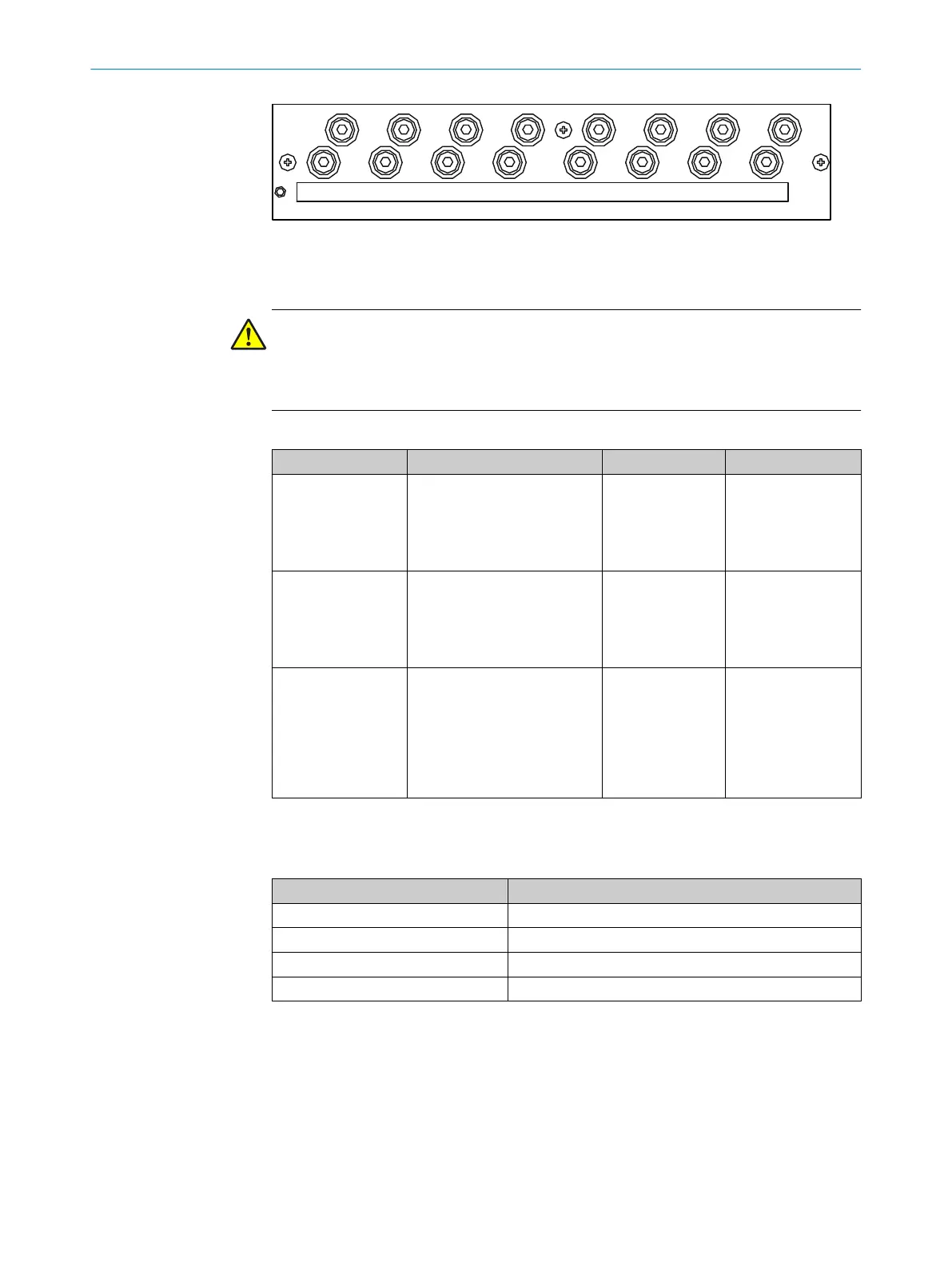
TUBE 1ELECTRONIC FILTER / PROBE 1 FILTER / PROBE 2 TUBE 3 CELLTUBE 2 DEVICE
Figure 128: Circuit breakers
10.12 Supply gases
NOTICE
Risk of contamination of analyzer
b
Observe the specified quality of the instrument air.
b
If required, provide for instrument air conditioning.
Table 35: Supply gases
Gas Quality Inlet pressure Flow rate
Instrument air (zero
gas quality)
Particle size max. 1 μm
Oil content max. 0.1 mg/m3
Pressure dew point max. –
40 °C
Purity class 2 (ISO 8573)
600 ... 700 kPa
(6.0 ... 7.0 bar)
Approx. 350 l/h
Instrument air solely
as induction air for
ejector
Particle size max. 5 μm
Oil content max. 1 mg/m3
Pressure dew point max.
+3 °C
Purity class 3 (ISO 8573)
500 ... 700 kPa
(5.0 ... 7.0 bar)
Approx. 1300 l/h
External span gas Precision: ± 2 %
Concentration: 80% ... 100%
of measuring range
The span gas must comply
with the specifications of the
standards to be applied (e.g.,
MARPOL Annex VI)
Max. 400 kPa
(4.0 bar)
Approx. 350 l/h
10.13 Tube connections
Table 36: Tube connections
Connection Dimension
Sample gas inlet Clamping ring screw connection 6 mm
Ejector induction air DN 6/8
Span gas inlet Clamping ring screw connection 6 mm
Gas outlet DN 8/10
10.14 Torques
Tighten all screw connections, for which no tightening torque or no pretension force is
specified in drawings or Assembly Instructions, according to VDI 2230.
TECHNICAL DATA 10
8017585/YXD9/V3-1/2017-05 | SICK T E C H N I C A L I N F O R M A T I O N | MARSIC300
87
Subject to change without notice