•
Secure the screw fittings against loosening.
•
Drilling plan: See dimension drawings above.
•
Install the enclosure horizontal.
2.9 Connect the sample gas line to the analyzer
WARNING
Danger to life by electric voltage
b
Only allow an authorized electrician to work on the electric system
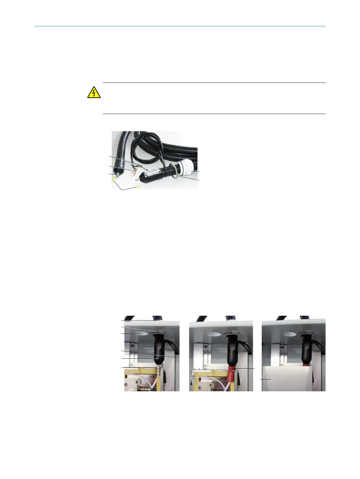
Connect heated sample gas line to analyzer
Figure 7: Heated sample gas line
1
Connection side without electric connec‐
tions on gas sampling system
2
Connection side with electric connec‐
tions on analyzer
3
Protective cap
4
2 x Pt100 connections (1 as reserve)
5
Power supply
6
Cable gland
7
Counter nut
The flexible wires of the heated sample
gas line are numbered.
Line assignment: see "Heated sample
gas lines", page 81
1. Unscrew counter nut from the cable gland and pull off the sample gas line.
2. Lead sample gas line together with electrical connections from above through the
housing opening on the analyzer.
3. Push counter nut back over the sample gas line and electric connections.
Figure 8: Sample gas line - connection diagram
1
Sample gas line 1
2
Sample gas line 2 (option)
3
Cable gland
4
Counter nut
5
Clamping ring screw connection (cell)
2 INSTALLATION
14
T E C H N I C A L I N F O R M A T I O N | MARSIC300 8017585/YXD9/V3-1/2017-05 | SICK
Subject to change without notice